ESP32-S3-WROOM-1 Pinout (N16R8)
ESP32-S3-WROOM-1 · ESP32-S3-WROOM-1 module, 18 × 25.5 × 3.1 mm
The ESP32-S3-WROOM-1 brings 36 GPIOs out to 41 pads. On the N16R8, three of them belong to the octal PSRAM, four are strapping pins, and two carry the native USB.
Checked against the KiCad library and datasheet on
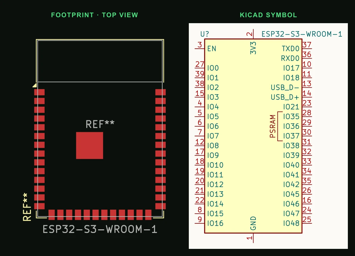
Pin by pin
| Pin | Name | Function |
|---|---|---|
| 1 | GND | Ground |
| 2 | 3V3 | Supply, 3.0 to 3.6 V. The supply must deliver at least 0.5 A |
| 3 | EN | High enables the chip, low powers it off. Never leave it floating |
| 4 | IO4 | GPIO4, TOUCH4, ADC1_CH3 |
| 5 | IO5 | GPIO5, TOUCH5, ADC1_CH4 |
| 6 | IO6 | GPIO6, TOUCH6, ADC1_CH5 |
| 7 | IO7 | GPIO7, TOUCH7, ADC1_CH6 |
| 8 | IO15 | GPIO15, U0RTS, ADC2_CH4, XTAL_32K_P |
| 9 | IO16 | GPIO16, U0CTS, ADC2_CH5, XTAL_32K_N |
| 10 | IO17 | GPIO17, U1TXD, ADC2_CH6 |
| 11 | IO18 | GPIO18, U1RXD, ADC2_CH7, CLK_OUT3 |
| 12 | IO8 | GPIO8, TOUCH8, ADC1_CH7. SDA in the Arduino core |
| 13 | IO19 | USB D− (native USB Serial/JTAG and USB OTG), GPIO19, U1RTS, ADC2_CH8 |
| 14 | IO20 | USB D+ (native USB Serial/JTAG and USB OTG), GPIO20, U1CTS, ADC2_CH9 |
| 15 | IO3 | Strapping: JTAG source, ignored unless an eFuse is burnt. No internal pull. TOUCH3, ADC1_CH2 |
| 16 | IO46 | Strapping: boot mode and ROM log. Weak pull-down |
| 17 | IO9 | GPIO9, TOUCH9, ADC1_CH8, FSPIHD. SCL in the Arduino core |
| 18 | IO10 | GPIO10, TOUCH10, ADC1_CH9, FSPICS0. SS in the Arduino core |
| 19 | IO11 | GPIO11, TOUCH11, ADC2_CH0, FSPID. MOSI in the Arduino core |
| 20 | IO12 | GPIO12, TOUCH12, ADC2_CH1, FSPICLK. SCK in the Arduino core |
| 21 | IO13 | GPIO13, TOUCH13, ADC2_CH2, FSPIQ. MISO in the Arduino core |
| 22 | IO14 | GPIO14, TOUCH14, ADC2_CH3, FSPIWP |
| 23 | IO21 | GPIO21 |
| 24 | IO47 | GPIO47, SPICLK_P_DIFF. 1.8 V I/O on the N16R16VA only |
| 25 | IO48 | GPIO48, SPICLK_N_DIFF. 1.8 V I/O on the N16R16VA only |
| 26 | IO45 | Strapping: flash supply voltage (VDD_SPI). Weak pull-down; keep it low at reset |
| 27 | IO0 | Strapping: boot mode. Weak pull-up; low at reset (with IO46 low) enters download mode |
| 28 | IO35 | Taken by the octal PSRAM on N16R8 (and every R8/R16V module). GPIO35 on modules without it |
| 29 | IO36 | Taken by the octal PSRAM on N16R8 (and every R8/R16V module). GPIO36 on modules without it |
| 30 | IO37 | Taken by the octal PSRAM on N16R8 (and every R8/R16V module). GPIO37 on modules without it |
| 31 | IO38 | GPIO38, FSPIWP |
| 32 | IO39 | GPIO39, MTCK (JTAG), CLK_OUT3 |
| 33 | IO40 | GPIO40, MTDO (JTAG), CLK_OUT2 |
| 34 | IO41 | GPIO41, MTDI (JTAG), CLK_OUT1 |
| 35 | IO42 | GPIO42, MTMS (JTAG) |
| 36 | RXD0 | U0RXD, GPIO44. The UART0 used for flashing and the boot log |
| 37 | TXD0 | U0TXD, GPIO43. The UART0 used for flashing and the boot log |
| 38 | IO2 | GPIO2, TOUCH2, ADC1_CH1 |
| 39 | IO1 | GPIO1, TOUCH1, ADC1_CH0 |
| 40 | GND | Ground |
| 41 | EPAD | Ground, under the module. Soldering it is optional and improves cooling |
Things that catch people out
- N16R8 means 16 MB of Quad SPI flash and 8 MB of Octal SPI PSRAM. The octal PSRAM takes IO35, IO36 and IO37 (pads 28 to 30), so those three are not available for anything else.
- GPIO26 to GPIO34 are not on the pads; GPIO26 to GPIO32 connect to the flash and PSRAM inside the package. Of the 36 GPIOs on the pads, the N16R8 leaves 33.
- The firmware must be set for octal PSRAM. In ESP-IDF that is CONFIG_SPIRAM_MODE (Quad or Octal) under SPI RAM config. Octal PSRAM runs only in DTR mode, and the quad flash only in STR mode.
- Download mode needs IO0 low and IO46 low at reset. Both have weak pulls (IO0 up, IO46 down) that give a normal boot when nothing drives them.
- IO45 high at reset selects a 1.8 V flash supply. Every WROOM-1 except the N16R16VA runs its flash from 3.3 V, so keep IO45 low until the chip has booted.
- The strapping pins are read when EN goes high, and the datasheet asks for them to hold their level for at least 3 ms after that.
- R8 modules such as the N16R8 are rated for −40 to 65 °C ambient. Turning on PSRAM ECC raises that to 85 °C and costs 1/16 of the PSRAM.
Putting the ESP32-S3-WROOM-1 on a PCB
- Feed 3V3 from a supply that can deliver 0.5 A, with 22 µF and 0.1 µF at the module, as in Espressif's peripheral schematic.
- Put an RC delay on EN, usually 10 kΩ to 3V3 and 1 µF to ground, so the chip starts after its supply has settled. Add a reset button from EN to ground and a boot button or jumper from IO0 to ground.
- For native USB, run IO19 (D−) and IO20 (D+) as a pair to the USB connector and keep other parts off those two pins. A USB-C receptacle also needs its own 5.1 kΩ resistor on CC1 and on CC2.
- Put the antenna end at the edge of the board, and keep copper, parts and ground pour out from under it. The WROOM-1U uses an external antenna connector and has no keep-out.
- The ground pad (41) is optional, but soldering it helps with heat. Do not over-paste it, or the module sits too high for the edge pads to wet.
Designing a board around it? Read ESP32 PCB design: antenna, power, boot pins and USB.
Common questions
- What does N16R8 mean on the ESP32-S3-WROOM-1?
- 16 MB of Quad SPI flash and 8 MB of Octal SPI PSRAM. Espressif's ordering table rates R8 modules for −40 to 65 °C ambient.
- Which pins does the N16R8's PSRAM use?
- IO35, IO36 and IO37 (pads 28, 29 and 30). On modules with octal PSRAM they connect to the PSRAM and are not available for other uses.
- What are the ESP32-S3 strapping pins?
- GPIO0, GPIO3, GPIO45 and GPIO46. At reset GPIO0 has a weak pull-up, GPIO45 and GPIO46 weak pull-downs, and GPIO3 floats. GPIO0 and GPIO46 low together enter download mode.
- Which ESP32-S3 pins are SDA and SCL?
- There are no fixed ones: the GPIO matrix can route I²C to any free GPIO. The Arduino core's defaults are SDA on GPIO8 and SCL on GPIO9, which are pads 12 and 17 on the WROOM-1.
- Why does my N16R8 not find its PSRAM?
- Check the PSRAM type the firmware was built for. The N16R8's PSRAM is octal, so a build set for quad PSRAM cannot use it: select Octal in ESP-IDF's CONFIG_SPIRAM_MODE and rebuild.
Describe the board, say an ESP32-S3-WROOM-1 N16R8 with USB-C and an I²C sensor. When PCBEditor assigns the pins, it keeps peripherals off the strapping pins, the USB pair and IO35 to IO37.
Design an ESP32-S3 board →Sources
- Espressif ESP32-S3-WROOM-1 & WROOM-1U datasheet v1.8
- Espressif ESP32-S3 Series datasheet v2.2 (GPIO restrictions, strapping pins)
- ESP-IDF: SPI flash and external SPI RAM configuration (ESP32-S3)
- arduino-esp32: ESP32-S3 default pins (variants/esp32s3/pins_arduino.h)
- KiCad 9 libraries: symbol RF_Module:ESP32-S3-WROOM-1, footprint RF_Module:ESP32-S3-WROOM-1 (CC-BY-SA 4.0).