ATtiny85 Pinout
ATtiny85 · DIP-8 / SOIC-8
Eight-pin AVR with six usable I/O. Pin 1 is RESET and doubles as an I/O only if you burn a fuse that makes the chip hard to reprogram.
Checked against the KiCad library and datasheet on
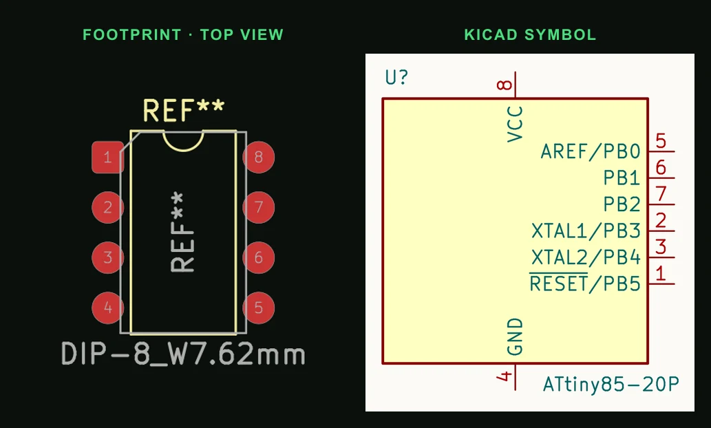
Pin by pin
| Pin | Name | Function |
|---|---|---|
| 1 | PB5 / RESET | Reset. Usable as I/O only with RSTDISBL fuse set. |
| 2 | PB3 / ADC3 | I/O, ADC, crystal XTAL1 |
| 3 | PB4 / ADC2 | I/O, ADC, PWM, crystal XTAL2 |
| 4 | GND | Ground |
| 5 | PB0 / MOSI / SDA | I/O, PWM, ISP MOSI, I²C data |
| 6 | PB1 / MISO | I/O, PWM, ISP MISO |
| 7 | PB2 / SCK / SCL | I/O, ADC1, INT0, ISP clock, I²C clock |
| 8 | VCC | Supply, 2.7–5.5 V (20 MHz needs 4.5 V or more) |
Things that catch people out
- Burning RSTDISBL to reclaim PB5 means you need a high-voltage programmer to recover the chip.
- ISP programming uses pins 1, 5, 6, 7 plus power.
- A crystal takes pins 2 and 3, leaving four I/O. The internal 8 MHz oscillator is enough for most projects.
Putting the ATtiny85 on a PCB
- 100 nF from pin 8 to pin 4, at the package.
- Keep a 10 kΩ pull-up on RESET and bring pins 1, 5, 6 and 7 plus VCC and GND to a 2×3 ISP header so the chip can be reprogrammed on the board.
- Anything wired to the ISP pins (5, 6, 7) must not load them so hard that programming fails; a series resistor of about 1 kΩ to an LED or input is usually enough.
Common questions
- Which ATtiny85 pins can do PWM?
- PB0, PB1 and PB4 (pins 5, 6 and 3) in the common Arduino cores. Timer1 can also drive PB3 as an inverted output.
- Does the ATtiny85 have I²C?
- Not a dedicated I²C peripheral, but its USI does I²C in software-assisted form on PB0 (SDA, pin 5) and PB2 (SCL, pin 7).
- How many I/O pins does the ATtiny85 have?
- Six (PB0 to PB5), but PB5 is RESET. In practice five, or four if you add a crystal.
Eight pins run out quickly. Describe what the ATtiny85 should drive and PCBEditor assigns the pins and routes a small board around it.
Design an ATtiny85 board →Sources
- Microchip ATtiny25/45/85 datasheet
- KiCad 9 libraries: symbol MCU_Microchip_ATtiny:ATtiny85-20P, footprint Package_DIP:DIP-8_W7.62mm (CC-BY-SA 4.0).