From an Arduino prototype to a custom PCB
The project works on the breadboard. Now it needs to fit in a box, survive being carried around, and stop falling apart when a jumper wire comes loose. Moving it onto a printed circuit board is the step most makers put off because it looks like a different skill. It is less of a jump than it looks, as long as you know what the Arduino board was doing for you.
Last reviewed
Short answer
Pick one of three routes: a shield that plugs onto the Uno, a board with a Nano-style module socketed on it, or a bare ATmega328P with its own clock, reset, decoupling and programming header. Draw the breadboard circuit as a schematic, lay out the board with connectors on the edges and capacitors at the chip, run the design-rule check against your fab’s limits, then order a few boards.
Three ways off the Uno
| Route | What you design | Best when |
|---|---|---|
| Shield | Only your circuit, on a board that plugs onto the Uno’s headers | You want it working this week and the Uno can stay in the build |
| Module on your board | Your circuit plus sockets for a Nano, Pro Mini or similar module | You need it smaller but don’t want to design the microcontroller circuit |
| Bare ATmega328P | Everything: clock, reset, decoupling, power, programming header | Size, cost per board or a production run matters |
There is no wrong answer here. Plenty of finished products are a module on a carrier board. If this is your first PCB, the module route gets you a real board with the fewest new things to get right.
What the Uno was doing for you
An Uno is not just a chip on a board. Around the ATmega328P it carries the clock, the reset circuit, decoupling capacitors, a regulator, and a second chip that turns USB into serial so the IDE can upload. The shield and module routes keep all of that. The bare-chip route means putting each piece on your own board.
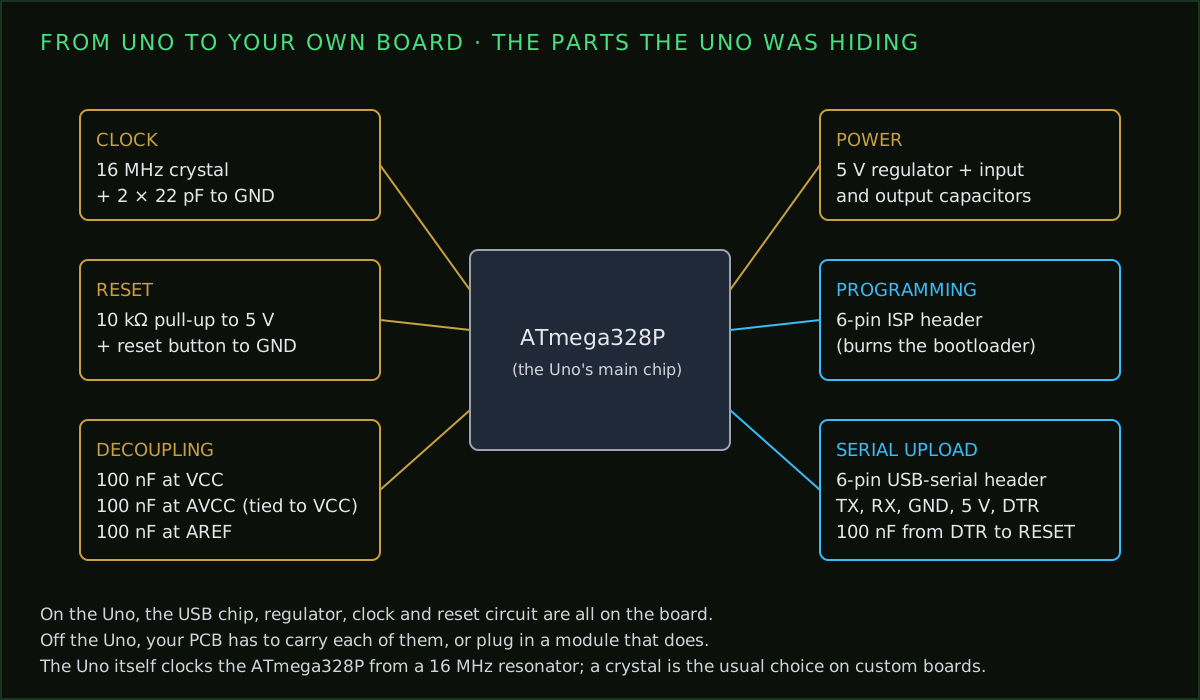
The missing decoupling capacitors
Turn the breadboard into a schematic
Before any layout, write down every connection as a schematic. This is where most first boards go wrong, because the breadboard hides mistakes that a PCB makes permanent. Go wire by wire, and use the chip’s real pin numbers rather than the Arduino names printed on the Uno.
| Arduino name | Port pin | DIP-28 pin |
|---|---|---|
| D0 / RX | PD0 | 2 |
| D1 / TX | PD1 | 3 |
| D2 | PD2 | 4 |
| D9 (PWM) | PB1 | 15 |
| D13 (LED) | PB5 | 19 |
| A0 | PC0 | 23 |
| A4 / SDA | PC4 | 27 |
| A5 / SCL | PC5 | 28 |
Every pin on the board should appear on exactly one net, and every net you meant to make should have at least two pins on it. Check the LED and resistor values while you are here; the LED resistor calculator does the arithmetic, and the Uno pinout shows what each header pin can do.
Layout rules for a first board
- Put connectors, buttons and anything you plug in on the board edges, where cables and fingers can reach them.
- Keep the crystal and its two capacitors right next to the XTAL pins, with short traces and nothing else routed under them.
- Place each decoupling capacitor at the pin it serves, not wherever there is room.
- Use two layers and give one of them mostly to a ground pour; it makes almost every other rule easier.
- Make power traces wider than signal traces. The trace width calculator gives the width for your current.
- Add mounting holes in the corners before you route, not after.
- Label connectors, polarity and pin 1 on the silkscreen; what those markings mean is worth a read before you design your own.
- Prefer through-hole or larger SMD parts (0805 and up) if you will solder the first boards by hand.
Doing it with AI, step by step
AI tools can now take a written description to a placed and routed board. Used well, that removes the slowest part of a first PCB. Used badly, it produces a board that looks finished and isn’t. The steps below keep it honest, shown on a real example: a small 5 V indicator board generated by PCBEditor from this description.
“Generate a compact 2-layer 5 V indicator PCB with exactly one 1x02 2.54 mm pitch power header J1 and three parallel LED branches. Each branch has its own 330 ohm 0805 resistor and 0805 LED: R1-D1 red, R2-D2 green, R3-D3 yellow. Connect J1 pin 1 to all resistor inputs; each resistor output to its LED anode; all LED cathodes to J1 pin 2. No other connectors or active ICs. Match part descriptions to real footprints, route every net, and report DRC honestly.”
- Describe the circuit precisely. Name the parts, the package sizes and the connections. The more exact the description, the less the tool has to guess.
- Review the plan before anything is built. Check the part list and the reason given for each part. Wrong parts are cheapest to fix here.
- Check the schematic. Every pin on one net, power and ground where they should be, LED polarity the right way round.
- Let it place and route, then read the report. You are looking for zero unrouted nets and a design-rule check with zero errors.
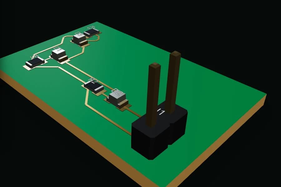
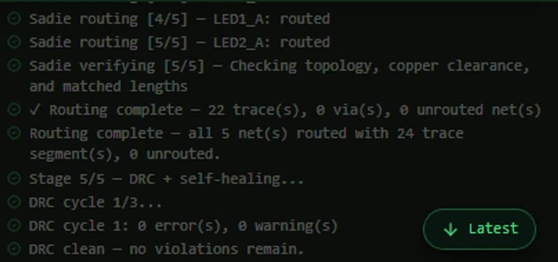
- Export the fabrication files and open them somewhere else. Load the Gerbers into a viewer that didn’t produce them, such as our free Gerber viewer, and look at every layer.
- Order a small batch. Five boards is enough to find out what you got wrong without paying for it ten times.
The point is not that the tool is never wrong; it is that each step has a check you can do yourself. The full flow from description to board is explained on the text to PCB page.
Getting code onto the new board
A shield or a module board programs exactly as before, through the Uno’s or the module’s own USB. A bare ATmega328P straight from the distributor usually has no Arduino bootloader, so it can’t accept an upload over serial until you give it one.
- Burn the bootloader once through the 6-pin ISP header. An Uno running the Arduino as ISP example sketch works as the programmer.
- From then on, upload sketches through a USB-to-serial adapter plugged into a 6-pin serial header on your board.
- The 100 nF capacitor from the adapter’s DTR line to the reset pin resets the chip at the start of each upload, the way the Uno does it.
You can also skip the bootloader and upload every sketch through the ISP header with a programmer. That frees the bootloader’s flash space and starts your code immediately at power-up.
Ordering the boards
Fabs want Gerber files for each layer, a drill file and, if they are assembling it, a bill of materials and a pick-and-place file. Run the design-rule check against your chosen fab’s minimum trace, gap and drill before exporting, then check the files in a viewer. Small two-layer boards are inexpensive at prototype quantities; the PCB cost estimator gives a rough figure for your size and quantity before you upload anything.
Common questions
- Can I copy the Arduino Uno PCB design?
- The Uno's reference design files are published under a Creative Commons share-alike licence, so you can build on them if you follow that licence. The Arduino name and logo are trademarks, so don't use them on your board.
- Do I need a crystal for a standalone ATmega328P?
- Not always. The chip has an internal 8 MHz oscillator, which needs matching fuse and board settings and is less accurate for timing and serial. Most Arduino-compatible boards use a 16 MHz crystal with two 22 pF capacitors.
- Should I make a shield or a standalone board?
- A shield is fastest and keeps the Uno's USB and power. A standalone board is smaller and cheaper per unit. A socketed Nano or Pro Mini module is the middle path: a small custom board without designing the microcontroller circuit.
- How do I program an ATmega328P on my own board?
- Burn the bootloader once through the 6-pin ISP header, for example with an Uno running the Arduino as ISP sketch, then upload sketches through a USB-to-serial adapter on a serial header with a 100 nF capacitor from DTR to reset.
- Can AI design my Arduino PCB?
- It can draft the schematic and, in tools with a real routing engine, place and route the board. You still review the parts, the pin connections and the design-rule report before ordering, the same as with any design.
Describe the project and get a board to review
Write what your breadboard does, which Arduino or module it uses and how it is powered. PCBEditor drafts the schematic, places and routes the board and runs the design-rule check, then shows you the report before you export anything.
Turn a project into a board→Sources
- Microchip Technology: ATmega328P datasheet (pin functions, clock options, decoupling).
- Arduino: Uno Rev3 published reference design and schematic.
- PCBEditor local generation, 3 October 2026: three-LED indicator board, 7 parts, 5 nets routed, DRC 0 errors and 0 warnings.