ESP32 PCB design: antenna, power, boot pins and USB, done right
Most custom ESP32 boards that fail don’t fail in the firmware. The Wi-Fi range is poor because there’s copper under the antenna, the chip resets whenever it transmits because the 3.3 V rail sags, or it never boots because a strapping pin is pulled the wrong way. All of these are decided on the PCB. This guide goes through each one for a board built around an ESP32 module.
Last reviewed
Short answer
Use a pre-certified module. Put its antenna at or past the board edge with no copper on any layer under or around it. Feed it from a regulator that can supply at least 500 mA, with bulk and 100 nF capacitors at the module’s 3V3 pin. Give EN a 10 kΩ pull-up and a 1 µF capacitor, add BOOT and RESET buttons, keep strapping pins free at reset, and on USB-C use a separate 5.1 kΩ resistor on each CC pin.
Module or bare chip?
An ESP32 module (ESP32-WROOM-32E, ESP32-S3-WROOM-1, ESP32-C3-MINI-1 and their relatives) already contains the chip, its flash, the crystal, the RF matching network and an antenna, and most are pre-certified for radio regulations. Designing the bare chip onto your own board means doing all of that yourself, including RF layout that has to be tuned and measured. Unless you are building thousands of units or need a smaller board than any module allows, use a module. The rest of this guide assumes one.
Pick the variant by what you need from it, not by habit. The original ESP32 has the most GPIOs and Bluetooth Classic, but no native USB. The ESP32-S3 adds native USB and more processing. The ESP32-C3 is smaller and cheaper, with native USB and fewer pins. That one choice decides half of the board: whether you need a USB-to-serial chip, and which pins are strapping pins.
Antenna placement and keep-out
The module’s PCB antenna is part of the module, but your board decides how well it works. Copper near the antenna, on any layer, detunes it and blocks radiation. Espressif’s guidelines and every module datasheet show a keep-out area for this, and the layout they recommend is the same: put the module on an edge of your board so the antenna sits at or beyond the edge, with no copper, traces, vias or parts under or around it.
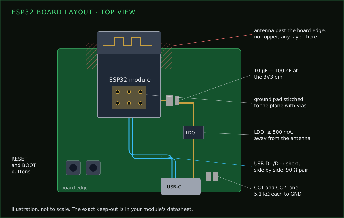
The ground pour that ruins the range
The same applies to what is around the board. A metal enclosure, a battery or a large connector next to the antenna does the same damage as copper on the board. If the product has a metal case, plan for an external antenna (a module variant with an antenna connector) from the start rather than fixing it later.
The 3.3 V rail
An ESP32 draws little current on average but takes short, sharp peaks when the radio transmits. Espressif recommends a supply that can deliver at least 500 mA. A regulator that is fine for the average sags on those peaks, the chip’s brownout detector fires, and the board resets every time it tries to connect to Wi-Fi. That symptom looks like a firmware bug and isn’t.
- From USB 5 V, a 3.3 V LDO rated for 500 mA or more works, for example the AP2112K-3.3 (600 mA). The popular AMS1117-3.3 also works from 5 V, but it needs over a volt of headroom and draws more quiescent current, which matters on a battery.
- From one Li-ion cell, the battery runs from about 4.2 V down to 3.0 V, so an ordinary LDO stops regulating well before the cell is empty. Use a low-dropout regulator and accept the cut-off, or a buck-boost converter if you need the whole capacity.
- At the module, put bulk capacitance (around 10 µF) and a 100 nF ceramic right at the 3V3 pin, as in the module datasheet’s reference schematic. The decoupling guide explains why distance matters.
A long, thin trace from the regulator adds its own drop on every peak. A 100 mm, 0.25 mm trace on 1 oz copper is about 0.2 Ω, which is 0.1 V lost at 500 mA. Keep the regulator close or use a wide trace; the trace resistance calculator shows the drop for your layout. Protecting the rail from reverse polarity and overvoltage is a separate job, covered in protecting the ESP32 power rail.
EN delay and boot buttons
EN (chip enable, called CHIP_PU on some parts) starts the chip when it goes high. If it rises at the same moment as a slowly ramping supply, the chip can start before its power is stable. Espressif’s reference design fixes this with an RC delay: a 10 kΩ pull-up to 3.3 V and a 1 µF capacitor to ground. A RESET button from EN to ground restarts the chip by hand.
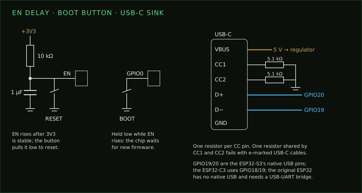
The chip reads its strapping pins at the moment EN goes high. On the ESP32 and ESP32-S3, holding GPIO0 low at that moment puts the chip into download mode, waiting for new firmware; the BOOT button does exactly that. On the ESP32-C3 the same job falls to GPIO9. Two buttons cost almost nothing and save you the day you need to recover a board with broken firmware.
Strapping pins
Strapping pins are ordinary GPIOs that the chip samples at reset to choose its boot mode and some settings. You can use them after boot, but anything you connect must not pull them the wrong way while the chip starts.
| Chip | Strapping pins | Watch out for |
|---|---|---|
| ESP32 (original) | GPIO0, GPIO2, GPIO5, GPIO12 (MTDI), GPIO15 (MTDO) | GPIO12 sets the flash voltage at boot. Pulled high by your circuit, a module with 3.3 V flash will not boot. |
| ESP32-S3 | GPIO0, GPIO3, GPIO45, GPIO46 | GPIO0 low at reset enters download mode. |
| ESP32-C3 | GPIO2, GPIO8, GPIO9 | GPIO9 low at reset enters download mode. |
GPIO12 on the original ESP32
Two more limits catch people on the original ESP32: GPIO6 to GPIO11 are wired to the module’s flash and are not available, and GPIO34 to GPIO39 are inputs only, with no internal pull-ups. The ESP32 pinout lists every pin and what it can do.
USB: native or a bridge
The ESP32-S3 and ESP32-C3 have native USB on fixed pins: GPIO19 (D−) and GPIO20 (D+) on the S3, GPIO18 (D−) and GPIO19 (D+) on the C3. Wire the connector straight to them; no extra chip is needed to program the board or print to a serial console. The original ESP32 has no USB of its own, so boards built on it use a USB-to-serial bridge such as a CP2102N or CH340, usually with two transistors that let the programming tool toggle EN and GPIO0, so you don’t have to press the buttons for every upload.
Route D+ and D− as a pair: side by side, the same length, as short as possible, over an unbroken ground plane, at about 90 Ω differential impedance. The differential pair calculator gives the width and gap for your stackup. Put a USB ESD protection array right at the connector, before the lines reach the chip.
One CC resistor is not enough
Layout checklist before you order
- The antenna is at or past the board edge, with a keep-out on every copper layer that matches the module datasheet.
- No pour, trace, via, part or mounting hole sits in the keep-out.
- The module’s ground pad is stitched to the ground plane with several vias.
- Bulk and 100 nF capacitors sit right at the 3V3 pin, and the regulator is rated for 500 mA or more.
- EN has its pull-up, its delay capacitor and a reset button; the boot strap has its button.
- No strapping pin is held the wrong way at reset by what you connected to it.
- USB D+ and D− run as a short pair over solid ground, with ESD protection at the connector.
- On USB-C, CC1 and CC2 each have their own 5.1 kΩ resistor to ground.
- The regulator and any switching converter sit away from the antenna.
- The design-rule check passes against your fab’s limits.
What PCBEditor does for you, and what it doesn’t
When you describe an ESP32 board, PCBEditor places antenna modules with the antenna flush at a board edge, uses the module footprint’s antenna courtyard so copper and parts stay out of that area, wires the EN pull-up and delay capacitor, and treats the strapping pins as reserved when it assigns GPIOs. Routing and the design-rule check are done by deterministic algorithms, not by the language model, so the result is checked geometry.
It does not tune or simulate the antenna, and it is not the tool for a bare-chip RF layout. Check the generated board against the checklist above and the keep-out drawing for your exact module before you order, the same review you would give any design.
Common questions
- Can I put a ground plane under the ESP32 antenna?
- No. Keep copper off every layer under and around the module's PCB antenna, as shown in the keep-out drawing in the module datasheet. The best layout puts the antenna at or past the board edge.
- How much current does an ESP32 board need?
- Espressif recommends a supply that can deliver at least 500 mA. Average current is much lower, but Wi-Fi transmit draws short peaks that make an undersized regulator sag and reset the chip.
- What capacitor goes on the ESP32 EN pin?
- Espressif's reference design uses a 10 kΩ pull-up to 3.3 V and a 1 µF capacitor to ground, so the chip starts only after the supply is stable. A reset button pulls EN to ground.
- Does the ESP32-S3 need a USB-to-serial chip?
- No. The ESP32-S3 and ESP32-C3 have native USB on fixed pins (GPIO19 and GPIO20 on the S3, GPIO18 and GPIO19 on the C3). The original ESP32 has no native USB and needs a bridge such as a CP2102N or CH340.
- Why does my USB-C ESP32 board not power up from some chargers?
- Usually because CC1 and CC2 share one resistor, or one is missing. A USB-C sink needs its own 5.1 kΩ pull-down on each CC pin; with a shared resistor, e-marked cables make the charger refuse power.
Describe the board and check what comes back
Tell PCBEditor which ESP32 module, how it is powered and what it connects to. It places the module with the antenna at an edge, keeps copper out of the antenna area, adds the EN pull-up and delay capacitor, routes the board and runs the design-rule check. Then review it against the checklist above.
Design an ESP32 board→Sources
Pin numbers, strapping pins and the EN circuit are from Espressif's own documents, checked 7 October 2026. Always confirm against the datasheet of the exact module you buy.
- Espressif Systems: ESP32 Hardware Design Guidelines; ESP32-S3 Hardware Design Guidelines; ESP32-C3 Hardware Design Guidelines.
- Espressif Systems: ESP32-WROOM-32E, ESP32-S3-WROOM-1 and ESP32-C3-MINI-1 module datasheets (peripheral schematics, keep-out drawings, strapping pins).
- USB Implementers Forum: USB Type-C Cable and Connector Specification (sink Rd pull-down on each CC pin).