Arduino Nano Pinout
Arduino Nano (ATmega328P) · 30-pin board, two rows of 15, 0.6 in apart
The Nano is an Uno's ATmega328P on a 30-pin board that plugs into a breadboard or a 0.6 in socket: the same I/O as the Uno, plus two analog-only inputs, A6 and A7.
Checked against the KiCad library and datasheet on
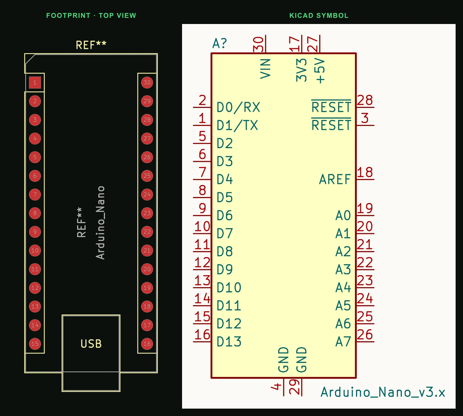
Pin by pin
| Pin | Name | Function |
|---|---|---|
| 1 | D1 / TX | UART transmit, also wired to the USB-serial chip |
| 2 | D0 / RX | UART receive, also wired to the USB-serial chip |
| 3 | RESET | Active-low reset (same net as pin 28) |
| 4 | GND | Ground |
| 5 | D2 | External interrupt INT0 |
| 6 | D3 ~ | PWM, external interrupt INT1 |
| 7 | D4 | Digital I/O |
| 8 | D5 ~ | PWM |
| 9 | D6 ~ | PWM |
| 10 | D7 | Digital I/O |
| 11 | D8 | Digital I/O |
| 12 | D9 ~ | PWM |
| 13 | D10 ~ | PWM, SPI SS |
| 14 | D11 ~ | PWM, SPI MOSI |
| 15 | D12 | SPI MISO |
| 16 | D13 | SPI SCK, on-board LED |
| 17 | 3V3 | 3.3 V output, small current (see below) |
| 18 | AREF | Analog reference input |
| 19 | A0 | Analog in; digital I/O 14 |
| 20 | A1 | Analog in; digital I/O 15 |
| 21 | A2 | Analog in; digital I/O 16 |
| 22 | A3 | Analog in; digital I/O 17 |
| 23 | A4 | Analog in, I²C SDA |
| 24 | A5 | Analog in, I²C SCL |
| 25 | A6 | Analog input only |
| 26 | A7 | Analog input only |
| 27 | +5V | 5 V out when powered from USB or VIN; 5 V in otherwise |
| 28 | RESET | Active-low reset |
| 29 | GND | Ground |
| 30 | VIN | Input to the on-board regulator, 7–12 V recommended |
Things that catch people out
- A6 and A7 reach the ADC but no I/O port, so digitalRead and pinMode do nothing on them.
- D0 and D1 are shared with the USB-serial chip. Anything connected to them can block uploads.
- Nanos made before 2018, and many clones (often with a CH340 USB chip), still have the old bootloader. If uploads time out, pick "ATmega328P (Old Bootloader)" as the processor in the Arduino IDE.
- The 3V3 pin is weak: on the original Nano it is the FT232RL's 3.3 V output, about 50 mA, and on clones it can be less. Do not run a radio module from it.
- 40 mA per I/O pin is the absolute maximum; Arduino recommends 20 mA.
Putting the Arduino Nano (ATmega328P) on a PCB
- Socketing a Nano: two 1×15 rows at 2.54 mm pitch, 15.24 mm (0.6 in) apart, 1.0 mm holes, as in KiCad's Module:Arduino_Nano.
- Put the USB end at the edge of your board so the cable still fits once the Nano is plugged in.
- Power it through VIN or +5V, not both from different supplies.
Designing a board around it? Read From an Arduino prototype to a custom PCB.
Common questions
- What is the difference between the Arduino Nano and Uno pinout?
- Same microcontroller and the same D0 to D13 and A0 to A5. The Nano adds A6 and A7 (analog only), drops the Uno's IOREF and separate SDA/SCL header, and puts everything on two breadboard-friendly rows.
- Which Arduino Nano pins are PWM?
- D3, D5, D6, D9, D10 and D11.
- Which Nano pins are I²C and SPI?
- I²C is A4 (SDA) and A5 (SCL). SPI is D10 (SS), D11 (MOSI), D12 (MISO) and D13 (SCK).
Outgrowing the breadboard? Describe the project and PCBEditor designs a board that the Nano plugs into, or a standalone ATmega328P board without it.
Turn a Nano project into a board →Sources
- Arduino Nano documentation
- Microchip ATmega328P
- KiCad 9 libraries: symbol MCU_Module:Arduino_Nano_v3.x, footprint Module:Arduino_Nano (CC-BY-SA 4.0).