555 Timer Pinout (NE555)
NE555 timer · DIP-8 / SOIC-8
The 555 timer in its 8-pin form: two comparators with thresholds at one third and two thirds of the supply, a flip-flop and a discharge transistor. Wire pins 2, 6 and 7 one way for a one-shot pulse, another way for an oscillator.
Checked against the KiCad library and datasheet on
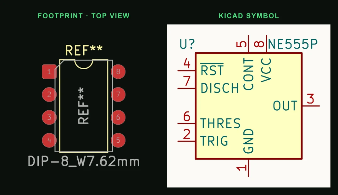
Pin by pin
| Pin | Name | Function |
|---|---|---|
| 1 | GND | Ground |
| 2 | TRIG | Starts a timing cycle when pulled below 1/3 VCC; the output goes high |
| 3 | OUT | Output; sources or sinks up to about 200 mA |
| 4 | RESET | Active low. Tie to VCC when not used |
| 5 | CONT | Control voltage, sits at 2/3 VCC. TI's example circuits put 10 nF from it to ground |
| 6 | THRES | Ends the cycle when it rises above 2/3 VCC; the output goes low |
| 7 | DISCH | Open-collector discharge: shorts the timing capacitor to ground while the output is low |
| 8 | VCC | Supply, 4.5 V to 16 V for the bipolar NE555 |
Things that catch people out
- A floating RESET (pin 4) resets the timer at random. Tie it to pin 8.
- The bipolar NE555 draws a sharp current spike from the supply every time the output switches. Decouple pin 8 with 100 nF plus 10 µF or more beside the chip.
- Oscillator (astable): R1 from VCC to pin 7, R2 from pin 7 to pins 6 and 2 joined, C from there to ground. f ≈ 1.44 / ((R1 + 2·R2)·C). One-shot (monostable): t ≈ 1.1·R·C.
- CMOS versions (TLC555, LMC555, ICM7555) have the same pinout and draw far less current. Most start at lower voltages (the TLC555's C grade from 2 V, the LMC555 from 1.5 V), but none drives 200 mA from pin 3: the TLC555 sinks about 100 mA and sources about 10 mA.
Putting the NE555 timer on a PCB
- Keep the timing capacitor's loop short: from pins 6 and 2 to the capacitor and straight back to pin 1. Do not share that ground return with whatever pin 3 is driving.
- Put the 10 nF on pin 5, if you fit one, and the supply decoupling on pin 8 right at the package.
- If pin 3 drives a relay or motor, add the flyback diode at the load and give that current its own path to the supply.
Common questions
- Is the NE555 pinout the same as the LM555 and TLC555?
- Yes. The 8-pin 555 timers from every maker share one pinout, bipolar and CMOS alike. The NE556 is two timers in a 14-pin package and has a different pinout.
- What does pin 5 on a 555 do?
- It is the internal 2/3 VCC threshold, brought out. Driving it shifts both thresholds, which changes the timing (that is how a 555 does voltage-controlled frequency). If you do not use it, TI's example circuits bypass it with 10 nF to ground, which usually improves noise immunity.
- Why does my 555 circuit reset or glitch at random?
- Usually a floating RESET pin or missing supply decoupling. Tie pin 4 to VCC and put 100 nF plus a larger capacitor across pins 8 and 1 at the chip.
Describe the 555 circuit you need, a 1 Hz LED flasher or a 10 s one-shot, and PCBEditor builds the schematic and a routed board, timing parts included.
Design a 555 timer board →Sources
- Texas Instruments NE555 datasheet
- KiCad 9 libraries: symbol Timer:NE555P, footprint Package_DIP:DIP-8_W7.62mm (CC-BY-SA 4.0).