Raspberry Pi Pico Pinout
Raspberry Pi Pico (RP2040) · 40-pin module, 2.54 mm pitch, castellated
The Pico puts the RP2040 on a 40-pin board: 26 of its 30 GPIO on the edge, three of them with an ADC, plus power pins that let it run from USB, a battery or an external rail.
Checked against the KiCad library and datasheet on
Pin by pin
| Pin | Name | Function |
|---|---|---|
| 1 | GP0 | SPI0 RX · UART0 TX · I²C0 SDA · PWM0 A |
| 2 | GP1 | SPI0 CSn · UART0 RX · I²C0 SCL · PWM0 B |
| 3 | GND | Ground |
| 4 | GP2 | SPI0 SCK · UART0 CTS · I²C1 SDA · PWM1 A |
| 5 | GP3 | SPI0 TX · UART0 RTS · I²C1 SCL · PWM1 B |
| 6 | GP4 | SPI0 RX · UART1 TX · I²C0 SDA · PWM2 A |
| 7 | GP5 | SPI0 CSn · UART1 RX · I²C0 SCL · PWM2 B |
| 8 | GND | Ground |
| 9 | GP6 | SPI0 SCK · UART1 CTS · I²C1 SDA · PWM3 A |
| 10 | GP7 | SPI0 TX · UART1 RTS · I²C1 SCL · PWM3 B |
| 11 | GP8 | SPI1 RX · UART1 TX · I²C0 SDA · PWM4 A |
| 12 | GP9 | SPI1 CSn · UART1 RX · I²C0 SCL · PWM4 B |
| 13 | GND | Ground |
| 14 | GP10 | SPI1 SCK · UART1 CTS · I²C1 SDA · PWM5 A |
| 15 | GP11 | SPI1 TX · UART1 RTS · I²C1 SCL · PWM5 B |
| 16 | GP12 | SPI1 RX · UART0 TX · I²C0 SDA · PWM6 A |
| 17 | GP13 | SPI1 CSn · UART0 RX · I²C0 SCL · PWM6 B |
| 18 | GND | Ground |
| 19 | GP14 | SPI1 SCK · UART0 CTS · I²C1 SDA · PWM7 A |
| 20 | GP15 | SPI1 TX · UART0 RTS · I²C1 SCL · PWM7 B |
| 21 | GP16 | SPI0 RX · UART0 TX · I²C0 SDA · PWM0 A |
| 22 | GP17 | SPI0 CSn · UART0 RX · I²C0 SCL · PWM0 B |
| 23 | GND | Ground |
| 24 | GP18 | SPI0 SCK · UART0 CTS · I²C1 SDA · PWM1 A |
| 25 | GP19 | SPI0 TX · UART0 RTS · I²C1 SCL · PWM1 B |
| 26 | GP20 | SPI0 RX · UART1 TX · I²C0 SDA · PWM2 A |
| 27 | GP21 | SPI0 CSn · UART1 RX · I²C0 SCL · PWM2 B |
| 28 | GND | Ground |
| 29 | GP22 | SPI0 SCK · UART1 CTS · I²C1 SDA · PWM3 A |
| 30 | RUN | RP2040 reset, active low. Pull to GND to restart the chip |
| 31 | GP26 | ADC0 · SPI1 SCK · UART1 CTS · I²C1 SDA · PWM5 A |
| 32 | GP27 | ADC1 · SPI1 TX · UART1 RTS · I²C1 SCL · PWM5 B |
| 33 | AGND | Analog ground for the ADC |
| 34 | GP28 | ADC2 · SPI1 RX · UART0 TX · I²C0 SDA · PWM6 A |
| 35 | ADC_VREF | ADC reference, a filtered 3.3 V on the board |
| 36 | 3V3(OUT) | 3.3 V from the on-board regulator. Keep loads under 300 mA |
| 37 | 3V3_EN | Pulled up to VSYS (100 kΩ); pull low to switch the 3.3 V regulator off, which also powers down the RP2040 |
| 38 | GND | Ground |
| 39 | VSYS | Main supply in, 1.8 V to 5.5 V |
| 40 | VBUS | USB 5 V, present only while USB is plugged in |
Things that catch people out
- GPIO are 3.3 V only and not 5 V tolerant. The ADC inputs (GP26 to GP28) have diodes to 3.3 V: keep them below it, and never drive them while the Pico is unpowered.
- Physical pin and GPIO numbers differ: GP0 is pin 1, but GP2 is pin 4 because pin 3 is a ground.
- GP23, GP24, GP25 and GP29 never reach the header. The board uses them for the regulator's mode, VBUS sensing, the LED and a VSYS/3 measurement on ADC3.
- Each GPIO can take any of the functions listed for it. The SDK's defaults are UART0 on GP0/GP1, I²C0 on GP4/GP5 and SPI0 on GP16 to GP19.
- To run from a battery on VSYS with USB also plugged in, feed the battery through a Schottky diode (or a P-MOSFET) so the two supplies cannot back-feed each other.
Putting the Raspberry Pi Pico (RP2040) on a PCB
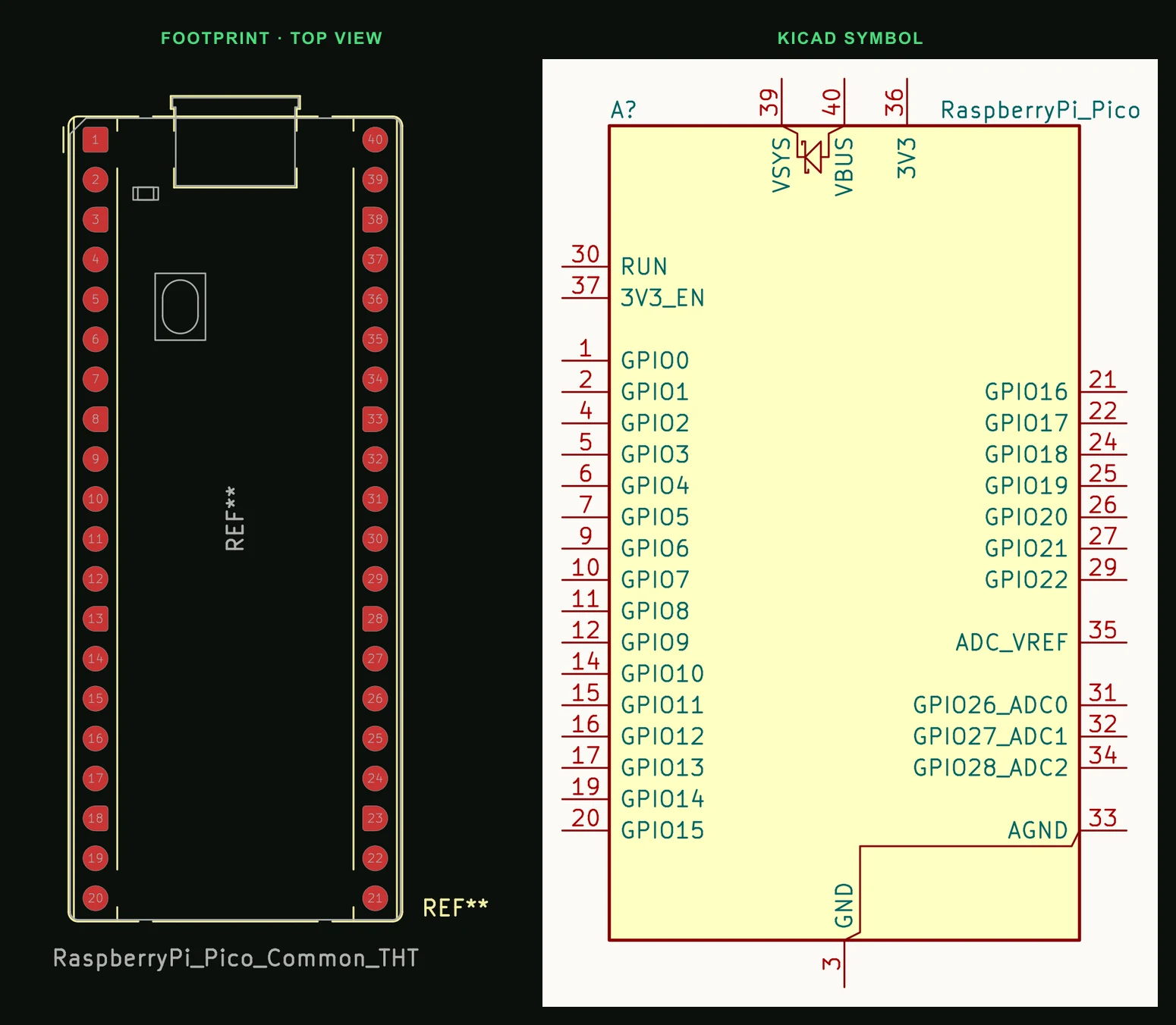
- As a module on your board: two rows of 20 at 2.54 mm pitch, 17.78 mm apart, 1.0 mm holes (KiCad Module:RaspberryPi_Pico_Common_THT). Or use the SMD footprint and solder the castellated edges flat.
- Seven GND pins and AGND run down both sides. Tie every one to your ground plane rather than picking one.
- Keep the three SWD debug pads (SWCLK, GND, SWDIO) reachable if you will ever need a debugger: on the Pico they are at the end opposite USB, on the Pico W mid-board. The Pico W's antenna is at the end opposite USB: keep copper and metal away from it.
Common questions
- Is the Pico W pinout the same as the Pico?
- The 40 header pins are the same. Inside, the Pico W uses GP23, GP24, GP25 and GP29 for its wireless chip (GP29 still reads VSYS/3, but only while GP25 is high), its LED hangs off the wireless chip rather than GP25, and the SWD debug pads move to the middle of the board.
- How many ADC pins does the Raspberry Pi Pico have?
- Three on the header: GP26, GP27 and GP28 (ADC0 to ADC2). The RP2040 also measures VSYS/3 on ADC3 and its own temperature sensor on ADC4.
- Can I power the Pico from 5 V?
- Yes. Feed 5 V into VSYS (pin 39), which accepts 1.8 V to 5.5 V, or into VBUS (pin 40). Never put 5 V on a GPIO or the 3V3 pin.
Describe the board the Pico plugs into and PCBEditor builds the schematic and a routed board around its 40 pins, grounds and power pins included.
Design a Pico carrier board →Sources
- Raspberry Pi Pico datasheet
- RP2040 datasheet (GPIO function table)
- KiCad 9 libraries: symbol MCU_Module:RaspberryPi_Pico, footprint Module:RaspberryPi_Pico_Common_THT (CC-BY-SA 4.0).