What the markings on a PCB mean
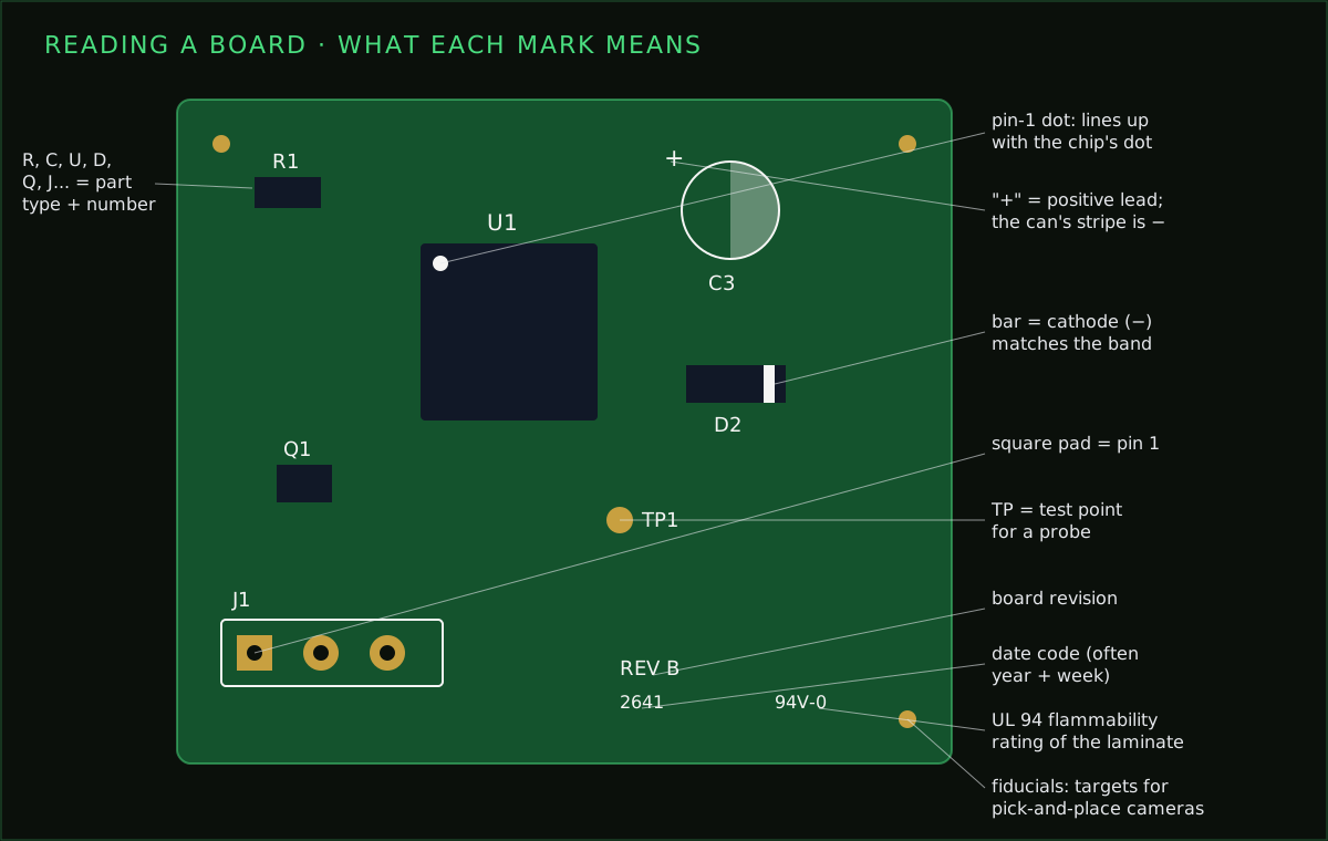
Pick up almost any circuit board and it is covered in small white letters, numbers, dots and lines. They aren’t decoration. They tell you what each part is, which way round it goes, and when and how the board was made. Once you know the handful of conventions behind them, you can find your way around a board you have never seen before.
Last reviewed
Short answer
A letter followed by a number is a reference designator: the letter is the part type (R resistor, C capacitor, U chip, D diode, Q transistor, J connector) and the number tells parts apart. Dots, notches, square pads and bars show pin 1 and polarity. Small print such as a date code, a revision and 94V-0 (a flammability rating) describes the board itself.
Reference designators: the letters
Every part on a board gets a reference designator: one or two letters for its type and a number that makes it unique, such as R1, C12 or U3. The same designator appears in the schematic and in the bill of materials, which is where you find the part’s actual value and part number. The letters follow common conventions, so you can usually tell what a part is from its label alone.
| Letters | Part type |
|---|---|
| R | Resistor |
| RN | Resistor network or array |
| RV / VR | Variable resistor, potentiometer |
| C | Capacitor |
| L | Inductor |
| FB | Ferrite bead |
| D | Diode (often LEDs too; some boards use LED) |
| Q | Transistor (bipolar or MOSFET) |
| U / IC | Integrated circuit |
| Y / X | Crystal or oscillator |
| J | Connector, usually the fixed socket |
| P | Connector, usually the plug |
| SW / S | Switch or button |
| K | Relay |
| F | Fuse |
| T | Transformer |
| BT | Battery or battery holder |
| JP | Jumper |
| TP | Test point |
| H / MH | Mounting hole or hardware |
| FID | Fiducial (a target for assembly cameras) |
The numbers usually say nothing about value or importance. They are assigned when the design is annotated, often left to right and top to bottom across the schematic, so R1 and R2 may sit at opposite ends of the board.
Pin 1 and polarity marks
Some parts only work one way round. The silkscreen shows which way, and the part has a matching mark on its body.
- Chips: a dot, a notch or a bevelled corner on the outline marks pin 1. It lines up with a dot or notch on the chip itself.
- Through-hole connectors and chips: the square pad is pin 1; the others are round.
- Diodes: a bar or line on the outline marks the cathode, matching the band on the diode body.
- LEDs: the cathode is usually shown by a line, a flat edge on the outline or a shaded side; on the LED itself it is the shorter leg or the flat on the rim.
- Electrolytic capacitors: the board marks the positive pad with a plus sign or shades the negative half. The stripe on the can marks the negative lead.
Tantalum capacitors are marked the other way
The small print about the board
- Revision (REV A, V1.2): which version of the design this is. Check it before following a schematic you found online.
- Date code: a four-digit number such as 2641 is often the year and week of manufacture, though the order varies between makers.
- 94V-0: the UL 94 flammability rating of the board material; V-0 is the strictest vertical-burn rating.
- UL logo and file number: the board maker’s UL recognition for that laminate and process.
- Fiducials: small round copper dots, usually in the corners, that pick-and-place machines use to line up the board.
- Order or panel numbers: some low-cost fabs print their own tracking number on the silkscreen unless you ask them to leave it off or put it somewhere specific.
- Layer numbers: on multilayer boards, small numbers near the edge sometimes show each copper layer, so you can check the stack is complete.
Markings on the parts themselves
The silkscreen tells you what a part is; the part’s own marking tells you its value or identity, when it has room for one.
- SMD resistors usually carry a three- or four-digit code: 103 is 10 × 10³ = 10 kΩ, 4701 is 4.7 kΩ. Through-hole resistors use colour bands; the resistor colour code calculator reads both kinds.
- Ceramic capacitors in small SMD packages usually have no marking at all. Through-hole ones use a three-digit picofarad code: 104 is 100 nF. The capacitor code decoder converts it.
- Transistors, diodes and small chips in tiny packages carry a short marking code (two or three characters) instead of the full part number. Search for the code together with the package name, for example the code plus “SOT-23”, to find candidates.
- Larger chips usually show the part number, a date code and a manufacturer logo, which is enough to find the datasheet.
Using the markings to repair or trace a board
With the board in front of you, start from the connectors (J) and the power parts (regulators are usually U, with inductors L and large capacitors C nearby) and follow the copper. Test points (TP) exist so a probe can reach important nets, and they are often labelled with the net name. If a part has burned and its marking is gone, its reference designator still tells you its type, and its neighbours often tell you its job.
If you are designing a board rather than reading one, the silkscreen guide covers what to put on yours so the next person can read it this easily.
Common questions
- What does R1 mean on a circuit board?
- R1 is a reference designator: R means resistor and 1 numbers it among the board's resistors. The same label appears in the schematic and the parts list, which is how you find the part's value.
- What does U mean on a PCB?
- U marks an integrated circuit, a chip. U1, U2 and so on number the chips on the board. Some boards use IC instead.
- What does 94V-0 mean on a PCB?
- It is the UL 94 flammability rating of the board material. V-0 is the strictest of the vertical-burn ratings: a test sample stops burning quickly and doesn't drip flaming material.
- How do I tell which way round a capacitor goes?
- On an aluminium electrolytic the stripe on the can marks the negative lead, and the board usually marks the positive pad with a plus sign or shades the negative side. Tantalum capacitors are the opposite: the stripe marks the positive end.
- How do I identify an SMD component with no clear marking?
- Start from the reference designator and the board's parts list if you have it. Resistors usually carry a value code; small capacitors usually carry nothing, so measure them. For chips and transistors, search the short marking code together with the package type.
Designing your own board?
PCBEditor places reference designators and footprints from real library parts, so every part on the board has a label that matches the schematic and the parts list, ready for whoever assembles or repairs it.
Start a board→Sources
Designator letters are conventions, not rules every board follows. When a board's parts list or schematic is available, it is the final word.
- ASME Y14.44 and IEEE 315: reference designation conventions for electrical and electronic parts.
- UL 94: Standard for Safety of Flammability of Plastic Materials (V-0, V-1, V-2 ratings).