Raspberry Pi GPIO Pinout
Raspberry Pi 40-pin header · 40-pin 2.54 mm header
Every 40-pin Pi (2, 3, 4, 5, Zero) puts power, ground and each GPIO on the same pins. Physical pin numbers and BCM GPIO numbers are different schemes — mixing them up is the usual cause of a circuit that does nothing.
Checked against the KiCad library and datasheet on
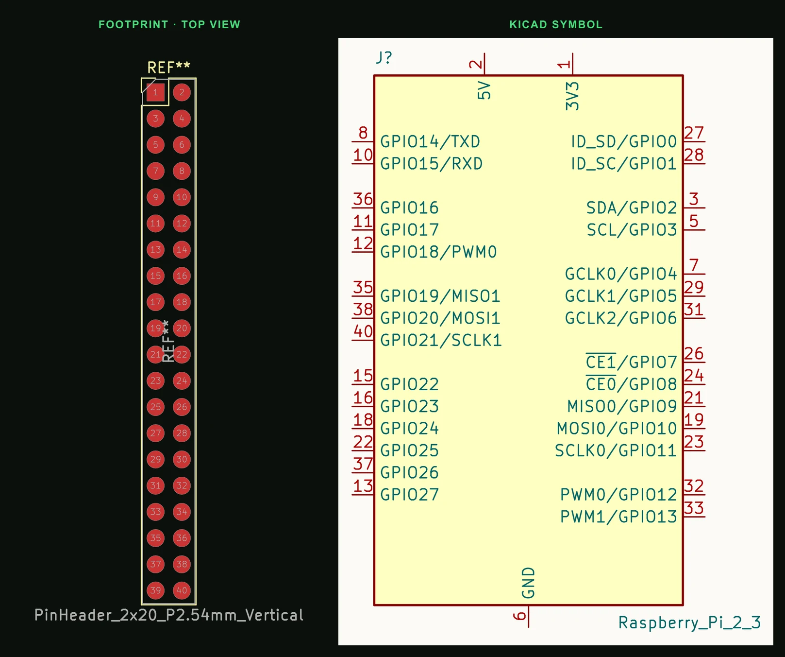
Pin by pin
| Pin | Name | Function |
|---|---|---|
| 1 | 3V3 | 3.3 V power from the Pi's regulator |
| 2 | 5V | 5 V power, straight from the supply |
| 3 | GPIO2 | I²C1 SDA (1.8 kΩ pull-up on the board) |
| 4 | 5V | 5 V power |
| 5 | GPIO3 | I²C1 SCL (1.8 kΩ pull-up on the board) |
| 6 | GND | Ground |
| 7 | GPIO4 | GPCLK0; default 1-Wire pin |
| 8 | GPIO14 | UART TXD |
| 9 | GND | Ground |
| 10 | GPIO15 | UART RXD |
| 11 | GPIO17 | General purpose |
| 12 | GPIO18 | PWM0, PCM clock |
| 13 | GPIO27 | General purpose |
| 14 | GND | Ground |
| 15 | GPIO22 | General purpose |
| 16 | GPIO23 | General purpose |
| 17 | 3V3 | 3.3 V power |
| 18 | GPIO24 | General purpose |
| 19 | GPIO10 | SPI0 MOSI |
| 20 | GND | Ground |
| 21 | GPIO9 | SPI0 MISO |
| 22 | GPIO25 | General purpose |
| 23 | GPIO11 | SPI0 SCLK |
| 24 | GPIO8 | SPI0 CE0 |
| 25 | GND | Ground |
| 26 | GPIO7 | SPI0 CE1 |
| 27 | GPIO0 | ID_SD: HAT ID EEPROM data. Reserved |
| 28 | GPIO1 | ID_SC: HAT ID EEPROM clock. Reserved |
| 29 | GPIO5 | GPCLK1 |
| 30 | GND | Ground |
| 31 | GPIO6 | GPCLK2 |
| 32 | GPIO12 | PWM0 |
| 33 | GPIO13 | PWM1 |
| 34 | GND | Ground |
| 35 | GPIO19 | SPI1 MISO, PWM1, PCM frame sync |
| 36 | GPIO16 | SPI1 CE2 |
| 37 | GPIO26 | General purpose |
| 38 | GPIO20 | SPI1 MOSI, PCM data in |
| 39 | GND | Ground |
| 40 | GPIO21 | SPI1 SCLK, PCM data out |
Things that catch people out
- GPIO is 3.3 V only. 5 V on any GPIO pin will damage the SoC — there is no tolerance.
- Pins 3 and 5 already carry 1.8 kΩ pull-ups; do not add your own.
- Ground is on pins 6, 9, 14, 20, 25, 30, 34 and 39.
- Pins 27 and 28 belong to a HAT's ID EEPROM. Leave them free unless you are building that EEPROM.
- The Pi 5 drives the header through its RP1 chip. The pins are the same, but libraries that write the old SoC's registers directly, such as RPi.GPIO, do not work on it; gpiozero (through its lgpio pin factory) and libgpiod do.
- The PWM channels in the table are the Pi 2, 3, 4 and Zero's. On the Pi 5, GPIO12, 13, 18 and 19 are four separate PWM0 channels, and some other alternate functions differ too.
Putting the Raspberry Pi 40-pin header on a PCB
- A HAT-sized board is 65 × 56 mm (65 × 56.5 mm with a surface-mount header) with the header along one long edge and four M2.5 holes, drilled 2.75 mm, on a 58 × 49 mm pattern. The original HAT specification has since been superseded by HAT+.
- Use a 2×20 female header on your board. Pin 1 is the square pad; check that it lands at the corner the Pi's pin 1 does, or the board plugs in mirrored.
- Drawing power from pins 2 and 4 takes it straight from the Pi's supply. Budget the Pi's own draw before hanging motors or LED strips off them.
Common questions
- What is the difference between BCM and physical pin numbers?
- Physical numbers count the header's pins 1 to 40. BCM numbers are the GPIO names the software uses. GPIO17 is physical pin 11, for example. Most libraries, gpiozero included, take BCM numbers.
- Which Raspberry Pi pins are I²C, SPI and UART?
- I²C1 is GPIO2 and GPIO3 (pins 3 and 5). SPI0 is GPIO10, 9 and 11 with chip selects on GPIO8 and GPIO7 (pins 19, 21, 23, 24, 26). The UART is GPIO14 and GPIO15 (pins 8 and 10).
- Is the Raspberry Pi 5 GPIO pinout the same as the Pi 4?
- Power, ground and every GPIO number sit on the same pins, and I²C1, SPI0 and the UART are where they were. Some alternate functions differ (GPIO12 and GPIO18 are separate PWM channels on the Pi 5), and software needs libraries that support its RP1 I/O chip: gpiozero through lgpio, or libgpiod. RPi.GPIO does not work.
Making a HAT? Describe what sits on top of the 40-pin header and PCBEditor builds the board with the 2x20 header in place.
Design a Pi add-on board →Sources
- Raspberry Pi documentation: GPIO and the 40-pin header
- Raspberry Pi HAT specification
- KiCad 9 libraries: symbol Connector:Raspberry_Pi_2_3, footprint Connector_PinHeader_2.54mm:PinHeader_2x20_P2.54mm_Vertical (CC-BY-SA 4.0).