ESP32 Pinout
ESP32-WROOM-32 · ESP32-WROOM-32 module / DevKitC
The ESP32 has far more I/O than the ESP8266, but several pins are input-only, several are tied to the internal flash, and a few decide boot mode.
Checked against the KiCad library and datasheet on
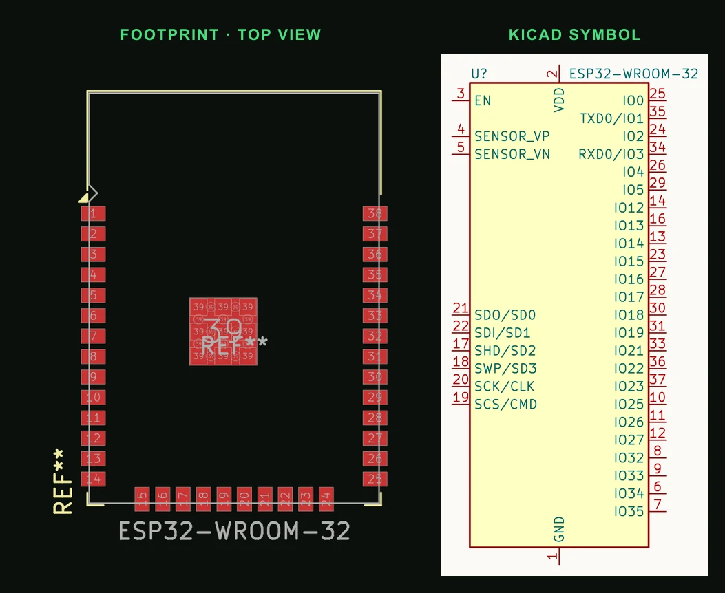
Pin by pin
| Pin | Name | Function |
|---|---|---|
| GPIO0 | Boot | Strapping: LOW at reset enters download mode |
| GPIO2 | Boot | Strapping: must be LOW or floating to enter download mode |
| GPIO5 | Strapping | Sets SDIO slave timing at boot. Usable after boot |
| GPIO12 | MTDI | Strapping: HIGH at boot selects 1.8 V flash, and the WROOM-32's 3.3 V flash then fails to boot |
| GPIO15 | MTDO | Strapping: LOW at boot silences the boot log on UART0 |
| GPIO34 | Input only | No output driver, no internal pull-up or pull-down |
| GPIO35 | Input only | No output driver, no internal pull-up or pull-down |
| GPIO36 | SVP, input only | ADC1 |
| GPIO39 | SVN, input only | ADC1 |
| GPIO21 | SDA | Default I²C data |
| GPIO22 | SCL | Default I²C clock |
| GPIO6–11 | Flash | Connected to internal SPI flash — never use |
Things that catch people out
- GPIO6 through GPIO11 are the flash interface. Using them stops the chip booting.
- ADC2 cannot be read while Wi-Fi is active — use ADC1 pins for anything sampled during a connection.
- Safe outputs with no boot duty: GPIO4, 13, 14, 16 to 19, 21 to 23, 25 to 27, 32 and 33.
Putting the ESP32-WROOM-32 on a PCB
- EN needs a 10 kΩ pull-up and about 1 µF to ground, so the chip comes out of reset after its supply is stable.
- Connect the exposed ground pad (39) with several vias to the ground plane; it carries heat as well as ground.
- Keep copper, parts and ground pour out from under the antenna end, and put that end at the edge of the board.
Designing a board around it? Read ESP32 PCB design: antenna, power, boot pins and USB.
Common questions
- Which ESP32 pins are safe to use?
- GPIO4, 13, 14, 16 to 19, 21 to 23, 25 to 27, 32 and 33 have no boot duty. GPIO34 to 39 are inputs only, and GPIO6 to 11 belong to the flash.
- Why does my ESP32 not boot when something is connected?
- A strapping pin is in the wrong state at reset. The usual one is GPIO12 pulled high, which selects 1.8 V flash; GPIO0 or GPIO2 held low has a similar effect on boot mode.
- Can ESP32 ADC2 pins be used with Wi-Fi?
- No. The Wi-Fi driver uses ADC2, so reads fail while Wi-Fi is on. Use the ADC1 pins (GPIO32 to 39) instead.
Copper under the antenna is the ESP32 mistake you only notice once the board arrives. PCBEditor keeps copper out of the module's antenna area when it lays out the board.
Design an ESP32 board →Sources
- Espressif ESP32-WROOM-32 datasheet
- Espressif ESP32 datasheet (strapping pins)
- KiCad 9 libraries: symbol RF_Module:ESP32-WROOM-32, footprint RF_Module:ESP32-WROOM-32 (CC-BY-SA 4.0).