Raspberry Pi HAT design guide: HAT+ rules for a Pi 5 board in KiCad
A HAT is the add-on board that sits on a Raspberry Pi’s 40-pin header, and since December 2023 the rules for it are Raspberry Pi’s HAT+ specification. The original HAT rules are deprecated. Here is what a HAT+ needs on the board, with Raspberry Pi’s values: the ID EEPROM, its address, the outline and keep-outs for a Pi 5, and power. It is drawn in KiCad 9, starting from the HAT template KiCad ships.
Last reviewed
Short answer
A Raspberry Pi HAT+ plugs into the 40-pin header and carries an ID EEPROM on pins 27 and 28. That is a 3.3 V, 16-bit-addressed 24Cxx part such as the CAT24C32, with 3.9 kΩ pull-ups to 3.3 V and its write-protect pin pulled up with 1 kΩ to a test point. The EEPROM’s address, 0x50 to 0x53, tells the Pi which class of HAT+ it is. The usual outline is 65 × 56.5 mm with four M2.5 holes on 58 × 49 mm, but HAT+ only requires one hole to line up. The board must work while the Pi is in STANDBY (5 V on, 3.3 V off). On a Pi 5 it should also leave room for the PoE header, for the camera, display and PCIe flex connectors, and for the Active Cooler (15 to 16 mm spacers). KiCad 9’s RaspberryPi-HAT template predates HAT+ and the Pi 5, so change its EEPROM write protection and keep-outs before you use it.
HAT vs HAT+: what changed
Raspberry Pi introduced HATs with the Model B+ in 2014. Its HAT+ specification (first release 8 December 2023, latest build 5 December 2024) replaces the original HAT rules, which are now deprecated, and makes four changes:
- A HAT+ must work in the STANDBY power state of the Pi 4 and later, where the 5 V rail is on and the 3.3 V rail is off.
- The physical dimensions are less prescriptive.
- The EEPROM holds less. It carries the name of a device tree overlay instead of the overlay itself, and the Pi loads the overlay from
/boot/firmware/overlays. - There are new classes: a Stackable HAT+ that can share a Pi with a normal HAT, and Power HAT+s.
The minimum for the name is short. The board plugs into the 40-way GPIO header, works in STANDBY if it takes power from the header, has an ID EEPROM with 3.9 kΩ pull-ups to 3.3 V, and fastens to at least one of the Pi’s mounting holes. A HAT+ is electrically backwards-compatible with older Pis, though they may need a firmware update. A board that does not follow the specification still works; it just cannot be sold as a HAT or HAT+.
The ID EEPROM circuit
At boot the Pi’s firmware looks for an EEPROM on ID_SD (GPIO0, pin 27) and ID_SC (GPIO1, pin 28), reads it, and loads the device tree overlay it names. That overlay is what sets up your pins and drivers. Raspberry Pi is specific about the part:
- a 24Cxx I²C EEPROM that runs at 3.3 V (not a 5 V-only part);
- 16-bit addressing, not 8-bit, and not a paged part whose low address bits select the page;
- a write-protect pin that protects the whole memory, and no I²C clock stretching;
- 100 kHz is enough.
Those rules rule out many small I²C EEPROMs. Raspberry Pi recommends onsemi’s CAT24C32, a 32 Kb (4 KB) part: its datasheet gives 1.7 to 5.5 V and hardware write protection for the entire memory.
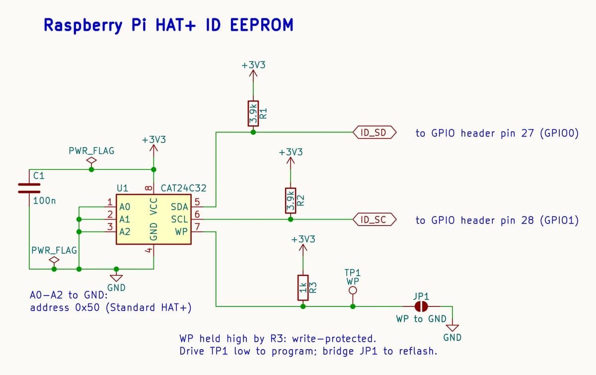
ID_SD and ID_SC each get a 3.9 kΩ pull-up to 3.3 V on the HAT. The write-protect pin goes to a test point and is pulled up to 3.3 V with 1 kΩ. That way the EEPROM is protected once the board leaves the factory, and the test fixture writes it by driving the test point low. The pull-up is stiff because the CAT24C32 pulls WP down internally. Raspberry Pi’s original design guide adds an optional jumper from WP to ground, so that a user can rewrite the EEPROM on purpose (JP1 in the figure).
Nothing else on pins 27 and 28
The EEPROM address is the HAT+ class
A HAT+ EEPROM answers at 101 00XY in binary, 0x50 to 0x53. The last two bits tell the firmware which class of board it is, so the EEPROM’s A0 and A1 pins choose the class:
| Address | Class | CAT24C32 pins | What the board may do |
|---|---|---|---|
| 0x50 | Standard | A0, A1, A2 to GND | Uses the GPIO pins, like every legacy HAT. HATs that also supply power are in this class too. |
| 0x51 | Stackable | A0 to 3.3 V; A1, A2 to GND | Uses only the ID pins and no GPIO from 2 to 27, so it can share a Pi with a Standard HAT+. |
| 0x52 | Power, MODE0 | A1 to 3.3 V; A0, A2 to GND | Powers the Pi but not its peripherals (about 3 A); no GPIO from 2 to 27. |
| 0x53 | Power, MODE1 | A0 and A1 to 3.3 V; A2 to GND | Powers the Pi and its peripherals (about 5 A); no GPIO from 2 to 27. |
A Pi can carry one HAT+ of each class at a time: a Standard HAT+ or legacy HAT, a Stackable HAT+ and a Power HAT+, up to three. The Stackable and Power classes need current firmware; older firmware does not know them. For a Power HAT+, the address also sets how much current the Pi tries to draw: MODE1 turns on usb_max_current_enable=1.
Tie the address pins straight to ground or 3.3 V. The CAT24C32 pulls them low inside when they float, which gives 0x50. onsemi notes that this pull-down is relatively strong, so whatever pulls an address pin high has to supply its current.
Outline, holes and the Pi 5
The Raspberry Pi 5 is 85 × 56 mm, with four ø2.7 mm holes for M2.5 screws on a 58 × 49 mm pattern, 3.5 mm in from the edges. Its 2 × 20 header is centred 29 mm from the left-hand holes. Raspberry Pi’s own HATs keep the original HAT size: the Sense HAT and the M.2 HAT+ are both 65 × 56.5 mm, the same width as the hole pattern plus 3.5 mm each side. HAT+ only requires the board to reach the whole 40-way header, ID pins included, and one hole to line up with a Pi hole. A smaller or odd-shaped board is allowed.
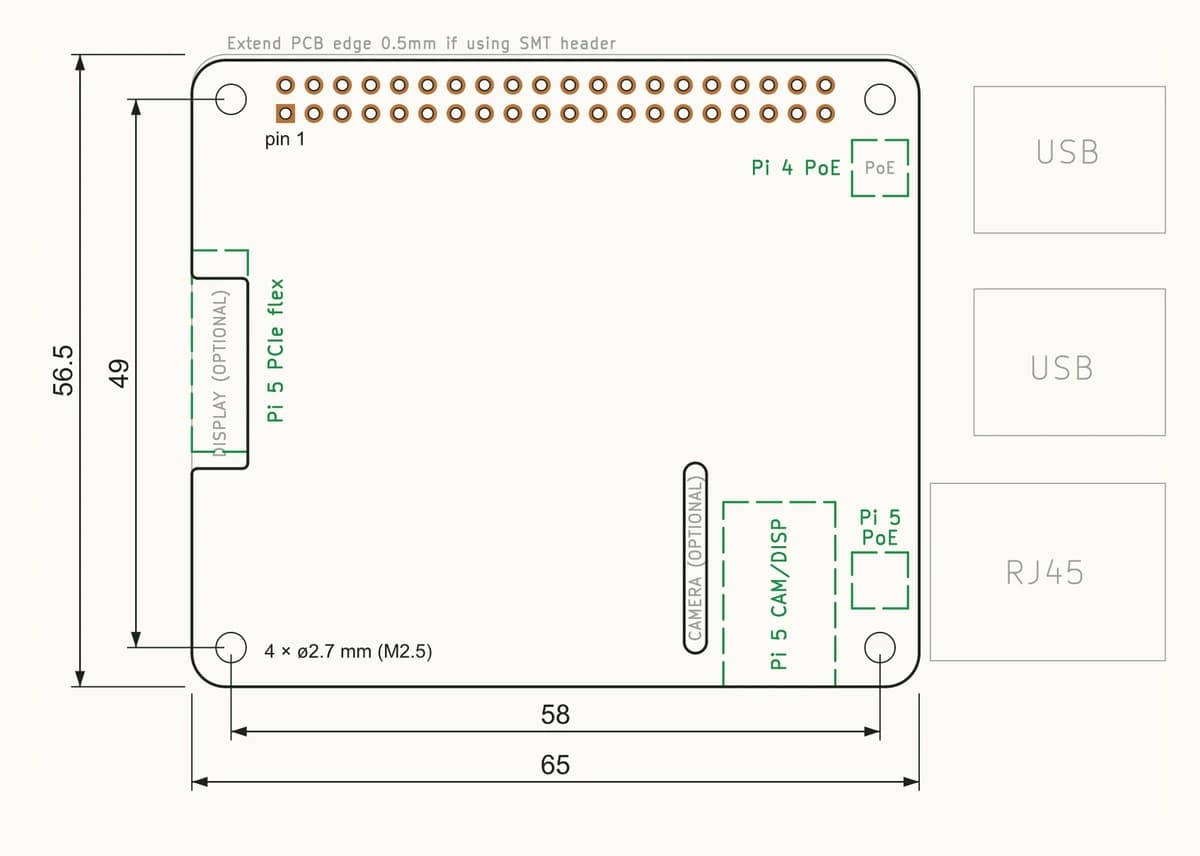
Raspberry Pi also recommends that a HAT+:
- does not foul the PoE header, which sits in a different place on each board. On a Pi 5 it is 6 mm above the lower-right hole; on a Pi 4 it is 42.86 mm above that hole, just under the top-right one;
- does not block the camera, display and PCIe flex connectors. On the Pi 5 the PCIe connector is on the left-hand short edge, and the two camera/display connectors sit near the bottom edge, between the second micro HDMI port and the Ethernet jack. Raspberry Pi’s M.2 HAT+ makes room with a 5 × 18 mm notch, 17.5 mm from the top edge, and a 10 × 16.5 mm cutout, 47.5 mm from the left edge;
- comes with a stacking header, spacers and screws that keep it clear of the Pi’s parts. With an Active Cooler fitted that means at least 15 mm between the boards, ideally 16 mm, and more if your HAT has parts on its underside.
KiCad’s RaspberryPi-HAT template: what to change
KiCad 9 ships two Raspberry Pi project templates: RaspberryPi-HAT and, for the Pi Zero size, RaspberryPi-uHAT (65 × 30 mm). Open one with File → New Project from Template. The HAT template already has a lot right:
- the board edge, 65 × 56 mm with 3 mm corners, plus a second edge on User.Drawings 0.5 mm higher for a surface-mount header;
- four 2.7 mm M2.5 holes, 3.5 mm in from each edge;
- a 2 × 20 socket with its pin 1 at 8.37 mm from the left edge, which centres the header 29 mm from the left-hand holes, as on the Pi 5 drawing;
- the ID EEPROM circuit with 3.9 kΩ pull-ups.
It was written for the original HAT specification, though, and its notes list models up to the Pi 4. Here is what we found when we exported its netlist with kicad-cli:
| What | In the template | For a Pi 5 HAT+ |
|---|---|---|
| Models | Pi 1 A+/B+, 2 B, 3 A+/B/B+ and 4 B, to the original HAT mechanical specification | For a Pi 5 board, add the Pi 5 keep-outs below and mark the board with the models it fits |
| EEPROM | CAT24C256, no footprint assigned | Any 3.3 V, 16-bit-addressed 24Cxx with whole-array write protection; Raspberry Pi recommends the CAT24C32. Pick its footprint |
| Write protect | WP goes to 3.3 V only through JP1, an open solder jumper; with JP1 open the chip’s internal pull-down leaves it writable | 1 kΩ from WP to 3.3 V and a test point, so it leaves the factory protected; keep a jumper to GND only if users should reflash it |
| Address pins | A0 to A2 unconnected (the internal pull-downs give 0x50) | Tie them to GND, or to 3.3 V for a Stackable or Power HAT+ |
| ID pull-ups and decoupling | 3.9 kΩ on ID_SD and ID_SC, 100 nF on VCC | Keep |
| PoE keep-out | 5 × 5 mm under the top-right hole, the Pi 4 header | Add the Pi 5 one: 6 mm above the lower-right hole |
| Cutouts | A display notch and a camera slot for the cables of the boards the original specification covered | On a Pi 5, leave the PCIe flex and the two camera/display connectors reachable |
The template ships its EEPROM writable
Run KiCad’s electrical rule check on the template as shipped and it reports 26 dangling labels and three power pins not driven as errors, plus two library-mismatch warnings. None is a fault in a blank template. The labels are the header’s GPIO names, waiting for your circuit, and the power warning goes away once the rails have a source or a PWR_FLAG; the power pin page explains that one.
Power: STANDBY and Power HAT+s
A Pi 4 or Pi 5 can be set to shut down into STANDBY instead of the older warm standby: the power management chip stays powered from 5 V, and every other supply, the 3.3 V rail included, is off. A HAT+ powered from the header must be electrically compatible with that state, and must not assume either rail comes up first. In practice, check everything on your board that runs from 5 V. While the 3.3 V rail is off, nothing should drive a GPIO pin or feed current back into 3.3 V.
A HAT+ that powers the Pi through the 5 V pins is a Power HAT+, and it has its own rules:
- it must supply at least 3 A at 5.1 V, and Raspberry Pi strongly recommends 5 A (13 W PoE HAT+s are the exception);
- it must only source current, never sink it;
- it must stay safe if someone also plugs in the Pi’s USB-C supply.
Its device tree overlay can state the current it supplies, in mA, in /chosen/power. The original rules recommended an “ideal diode” safety circuit ahead of the 5 V of any board that back-powers the Pi through the header. Whatever you do, never connect a power source to the 3.3 V pins.
GPIO pins at power-on
At power-on every GPIO pin on the header is an input with a weak pull-up or pull-down. A HAT+ has to tolerate either, at any time, and must not assume they are applied or removed all at once. If a pin of yours must sit high or low from the start, such as an enable or a chip select, give it an external pull resistor. GPIO2 and GPIO3 (I²C1 SDA and SCL) are the exception: they already have pull-ups of about 2 kΩ to 3.3 V on the Pi. The original HAT rules also ask a board that drives GPIO6, 14 or 16 to protect itself against very old firmware, which could drive those pins as outputs at boot.
Every pin is 3.3 V only. For which pin carries which peripheral, see the Raspberry Pi GPIO pinout, which also covers what the Pi 5’s RP1 I/O chip changes for software.
Programming the EEPROM
The EEPROM holds:
- a product UUID, a vendor string and a product string (required);
- a product ID and a version (optional);
- the name of the board’s device tree overlay (recommended). Raspberry Pi suggests names of the form manufacturer-hatname; names starting with rpi- are reserved for Raspberry Pi.
The tools are in Raspberry Pi’s utils repository, under eeptools. To program a board:
- Fill in a copy of
eeprom_settings.txtand build the image witheepmake myhat_eeprom.txt myhat.eep. Keep the UUID eepmake generates in your settings file. - Disable write protection by pulling the WP test point low.
- Create a software I²C bus on the ID pins with
sudo dtoverlay i2c-gpio i2c_gpio_sda=0 i2c_gpio_scl=1 bus=9. The pins also belong to I²C0, which cameras and displays use. - Check that
i2cdetect -y 9shows the EEPROM at 50. - Write the image with
sudo ./eepflash.sh -w -t=24c32 -a=0x50 -f=myhat.eep. - Re-enable write protection.
Marking and naming
A compliant board should carry the HAT+ wordmark on its silkscreen; Raspberry Pi publishes it as SVG, EPS and a CAD symbol. The product name should include “HAT+”, as in “Raspberry Pi M.2 HAT+ M Key”. A HAT+ may fit only some Pi models, electrically or mechanically. If so, it must say which models on the board itself and in its documentation, as a board shaped around the Pi 5’s keep-outs would.
A HAT+ checklist
| Item | What Raspberry Pi asks for |
|---|---|
| Header | 2 × 20, 2.54 mm, connecting to the whole header, ID_SD (pin 27) and ID_SC (pin 28) included |
| ID EEPROM | 3.3 V 24Cxx, 16-bit addressed, not paged, no clock stretching, whole-array WP; CAT24C32 recommended |
| Pull-ups | 3.9 kΩ from ID_SD and ID_SC to 3.3 V; 1 kΩ from WP to 3.3 V, to a test point |
| Address | 0x50 Standard, 0x51 Stackable, 0x52 or 0x53 Power HAT+ |
| Power states | Works in STANDBY (5 V on, 3.3 V off); no assumption about which rail comes up first |
| Power HAT+ | Sources current only; at least 3 A at 5.1 V, 5 A recommended; safe with the Pi’s USB-C supply also connected. Nothing ever drives the 3.3 V pins |
| GPIO defaults | External pulls wherever a pin must sit high or low at power-on; GPIO2 and GPIO3 already have about 2 kΩ to 3.3 V |
| Mechanical | At least one hole on a Pi hole (58 × 49 mm pattern, ø2.7 mm, M2.5); PoE headers, camera, display and PCIe flex left clear; 15 to 16 mm spacers for the Active Cooler |
| Silkscreen | HAT+ wordmark, and the supported models if the board fits only some |
Before you order, export the board’s Gerbers and look at them layer by layer. The Gerber check guide shows what to look for. On a HAT that means the outline with its notches, the four holes and the header drills.
Common questions
- What is the difference between a Raspberry Pi HAT and a HAT+?
- HAT+ is Raspberry Pi’s current specification for add-on boards (first released in December 2023), and the original HAT specification is deprecated. A HAT+ must work in the STANDBY power state of the Pi 4 and later, where 5 V is on and 3.3 V is off. Its EEPROM holds less: vendor and product strings, a UUID and the name of a device tree overlay, rather than the whole overlay. Its dimensions are less prescribed: one mounting hole must line up. It also adds Stackable and Power classes, chosen by the EEPROM address.
- What are the dimensions of a Raspberry Pi HAT?
- Raspberry Pi’s own HATs, such as the Sense HAT and the M.2 HAT+, are 65 × 56.5 mm with four holes on a 58 × 49 mm pattern, 3.5 mm in from the edges. That matches the Pi’s holes: 2.7 mm diameter for M2.5 screws. HAT+ itself only requires the board to plug into the 40-pin header and to line up with at least one Pi mounting hole. KiCad’s templates are 65 × 56 mm (plus 0.5 mm for a surface-mount header) for a HAT and 65 × 30 mm for a Pi Zero-sized uHAT.
- Does a Raspberry Pi HAT need an EEPROM?
- A board can only be called a HAT or HAT+ if it has a valid ID EEPROM on ID_SD and ID_SC (pins 27 and 28), with 3.9 kΩ pull-ups to 3.3 V. An add-on board without one still works, but it cannot use the HAT or HAT+ name or marking. If it has no EEPROM, leave pins 27 and 28 unconnected.
- What I2C address should a HAT EEPROM use?
- 0x50 for a normal (Standard) HAT+, which is every board that uses the GPIO pins. HAT+ also defines 0x51 for a Stackable HAT+ that uses only the ID pins, and 0x52 and 0x53 for Power HAT+s that supply about 3 A or about 5 A. Set the address with the EEPROM’s A0 and A1 pins.
- Is there a Raspberry Pi HAT template for KiCad?
- Yes. KiCad 9 ships two project templates, RaspberryPi-HAT and RaspberryPi-uHAT, with the board edge, the four mounting holes, the 2 × 20 socket in the right place, display and camera cutouts, a PoE keep-out and the ID EEPROM circuit. They follow the original HAT specification and list models up to the Pi 4. For a Pi 5 HAT+, change the EEPROM’s write protection to a 1 kΩ pull-up and test point, tie its address pins, and add the Pi 5 PoE and connector keep-outs.
- What standoff height do I need for a Raspberry Pi 5 HAT?
- Raspberry Pi recommends at least 15 mm between the Pi and a HAT+, and 16 mm is ideal, so that the Active Cooler fits underneath. Use taller spacers if your HAT has parts on its underside, and pick a header tall enough to match. The original HAT rule asked for at least 8 mm.
- Can a HAT power the Raspberry Pi through the GPIO header?
- Yes, through the 5 V pins; such a board is a Power HAT+. It must supply at least 3 A at 5.1 V, and Raspberry Pi strongly recommends 5 A. It must only source current and must stay safe if the Pi’s own USB-C supply is plugged in at the same time. Never connect a power source to the 3.3 V pins.
Bring the KiCad project into PCBEditor
PCBEditor opens KiCad projects in the browser: import the .kicad_pcb with its .kicad_sch files, or the zipped project, and the schematic’s nets come in by KiCad’s rules. Check the HAT’s outline and parts in 2D and 3D and run the design-rule check before you order.
Open the editor→Sources
Values in the schematic follow Raspberry Pi’s specification and design guide; the drawing is ours. Positions marked in green on the board are measured from the HAT+ specification’s figures, which Raspberry Pi gives as examples to start from: check them against the current Pi 5 mechanical drawing and your own spacers before you order.
- Raspberry Pi Ltd, Raspberry Pi HAT+ Specification (build 2024-12-05; first release 08 December 2023): chapter 1 (changes from the original HAT), chapter 2 (power states, GPIO power-on state, ID pins), chapter 3 (ID EEPROM, classes and addresses, stackability, EEPROM device rules, CAT24C32), chapter 4 (Power HAT+s), chapter 5 (marking), chapter 6 (electrical), chapter 7 and Figs. 2 to 4 (mechanical: Sense HAT, M.2 HAT+ M Key, PoE+ HAT), appendices A and B (EEPROM format and tools).
- Raspberry Pi, github.com/raspberrypi/hats (deprecated in favour of HAT+): README (basic requirements for add-on boards) and designguide.md (ID EEPROM circuit, write-protect jumper, back-powering, 3.3 V pins).
- Raspberry Pi Ltd, Raspberry Pi 5 mechanical drawing: 85 × 56 mm, mounting holes 58 × 49 mm at 3.5 mm from the edges, ø2.7 mm, header centred 29 mm from the left-hand holes.
- onsemi, CAT24C32 datasheet, Rev. 26 (May 2018): features, pin functions, note 5 (internal pull-downs on WP and A0 to A2), device addressing and hardware write protection.
- KiCad 9.0.9: the RaspberryPi-HAT and RaspberryPi-uHAT project templates (board, schematic and template notes), kicad-cli netlist, ERC and SVG export, used for both figures.