I²C pull-up resistor value: how to calculate it, with worked values for 3.3 V
Everyone has a default: 4.7 kΩ, sometimes 10 kΩ. Both work on a short bus at 100 kHz, which is why the habit survives. Move to 400 kHz, run the bus down a 30 cm cable, or plug in three breakout boards that each bring their own pair, and the default stops being right. The I²C specification gives two formulas that set the range; this page works them for 3.3 V and 5 V and checks real schematics against them.
Last reviewed
Short answer
The pull-up has a minimum and a maximum. The minimum is set by the supply and the current a device can sink: Rmin = (VDD − 0.4 V) / 3 mA, which is 0.97 kΩ at 3.3 V and 1.7 kΩ at 5 V ± 10 %. The maximum is set by the rise time and the bus capacitance Cb: Rmax = tr / (0.8473 × Cb), with tr = 1000 ns at 100 kHz and 300 ns at 400 kHz. At 3.3 V and 400 kHz, 2.2 kΩ covers a bus up to 161 pF; 4.7 kΩ only up to 75 pF. Fit one pair per bus, and count the pull-ups already on every module you connect: they add in parallel.
Why I²C needs pull-ups at all
SDA and SCL are open-drain: a device can pull a line low, and nothing on the bus ever drives it high. The pull-up resistor does that. When every device lets go, the resistor charges the line, and the wiring and pins on it (the bus capacitance) decide how fast. That charging edge is the whole story: too slow and a receiver sees a high late or not at all; too strong and the devices cannot pull the line low enough.
The specification sets both ends in its section 7.1, and the limits it uses are in its Table 10:
| Mode | SCL clock | Rise time max (tr) | Bus capacitance max (Cb) |
|---|---|---|---|
| Standard-mode | 100 kHz | 1000 ns | 400 pF |
| Fast-mode | 400 kHz | 300 ns | 400 pF |
| Fast-mode Plus | 1 MHz | 120 ns | 550 pF |
A device must be able to sink 3 mA while holding the line at or below 0.4 V in Standard-mode and Fast-mode, and 20 mA in Fast-mode Plus. A receiver reads below 0.3 VDD as low and above 0.7 VDD as high.
The minimum: supply voltage and sink current
The smaller the resistor, the more current flows through it while a device holds the line low. The device is only guaranteed to sink 3 mA at 0.4 V, so:
Rp(min) = (VDD - VOL(max)) / IOL

3.3 V:          (3.3 V - 0.4 V) / 3 mA = 0.97 kOhm
5 V +/- 10 %:   (5.5 V - 0.4 V) / 3 mA = 1.7 kOhm   (the specification's example, section 7.2.4)
Fast-mode Plus: (3.3 V - 0.4 V) / 20 mA = 145 Ohm
Use the highest supply voltage the board will see, as the specification’s 5 V example does. Below the minimum, a low may sit above 0.4 V and eat into the noise margin, and the parts run outside their rating. Some parts can sink more: Sensirion’s SHT4x datasheet allows pull-ups down to 390 Ω. The bus is only as strong as its weakest device, though, so size for 3 mA unless every part on it is rated for more.
The maximum: rise time and bus capacitance
A resistor charging a capacitor rises along V(t) = VDD(1 − e−t/RC). From 0.3 VDD to 0.7 VDD takes ln(7/3) × RC, which is 0.8473 × RC. Setting that equal to the allowed rise time gives the largest resistor that still makes the edge in time:
Rp(max) = tr / (0.8473 x Cb)

100 kHz, 100 pF:  1000 ns / (0.8473 x 100 pF) = 11.8 kOhm
400 kHz, 100 pF:   300 ns / (0.8473 x 100 pF) =  3.54 kOhm
400 kHz, 200 pF:   300 ns / (0.8473 x 200 pF) =  1.77 kOhm
Plot both limits against bus capacitance and the usable range is the band between them:
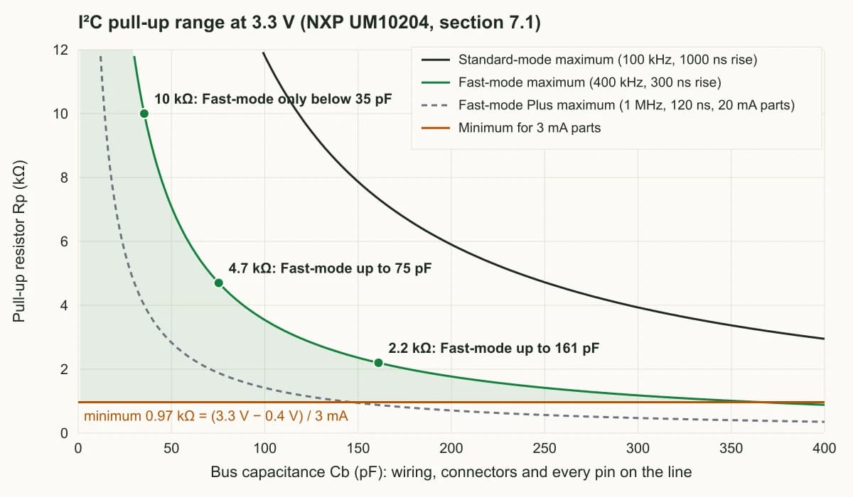
Two things stand out. At 400 kHz the band narrows fast: by 366 pF the Fast-mode maximum meets the 0.97 kΩ minimum, and no pull-up works with 3 mA parts. And the band is wide at 100 kHz, which is why almost any value seems fine until the clock goes up. Within the band, the specification’s advice is to go toward the high end on battery-powered designs, where the current through the resistor while a line is low matters.
Worked values at 3.3 V
The same formula, turned around: the largest bus capacitance at which each common value still meets the rise time, Cb = tr / (0.8473 × Rp).
| Pull-up | Current while low (at 0.4 V) | 100 kHz: up to | 400 kHz: up to |
|---|---|---|---|
| 1 kΩ | 2.9 mA (just inside 3 mA) | 1180 pF → limited by the 400 pF spec | 354 pF |
| 2.2 kΩ | 1.3 mA | 536 pF → 400 pF | 161 pF |
| 4.7 kΩ | 0.62 mA | 251 pF | 75 pF |
| 10 kΩ | 0.29 mA | 118 pF | 35 pF |
| 45 kΩ (ESP32-C3 internal) | 0.06 mA | 26 pF | 8 pF |
The 10 kΩ row is the one people meet in datasheets: Sensirion’s SHT4x quick-start circuit draws 10 kΩ pull-ups. That is a sound choice next to the sensor at 100 kHz, and the part supports 400 kHz and faster, but at 400 kHz 10 kΩ is only good for 35 pF of bus. Treat a datasheet’s pull-up value as an example for its figure, not as the value for your bus.
A pull-up is per bus, not per part
Finding your bus capacitance
Cb is everything on the line: each device pin (the specification allows up to 10 pF per pin), the PCB trace, connectors and any cable. A short bus on one board with two or three devices is usually well below 100 pF. A ribbon cable to another board can add more than all the chips together.
Measuring is better than guessing. On a scope, read the rise time from 30 % to 70 % of VDD on SCL and turn the formula around: Cb = tr / (0.8473 × Rp). A 400 ns edge with 4.7 kΩ pull-ups means about 100 pF, too slow for 400 kHz, and the fix is a smaller resistor, not a slower probe. The probe itself adds capacitance, so measure the edge, don’t judge the bus by whether it works with the probe on.
When the bus is long enough that no resistor fits, the specification’s section 7.2 lists the ways out: run the clock slower, use parts rated for Fast-mode Plus (20 mA drive), split the bus with a buffer such as the PCA9517, or use a switched pull-up that adds a strong pull only during the rising edge.
Multiple devices: pull-ups add in parallel
Breakout boards almost always carry their own pull-ups, so a bus of three breakouts has three pairs. In parallel they make a smaller resistance, which speeds the edge (fine) and raises the current a device must sink (not fine past 3 mA). How many identical boards one bus can take before the total drops below the minimum:
| Pull-ups on each board | 3.3 V bus (min 0.97 kΩ) | 5 V bus (min 1.7 kΩ) |
|---|---|---|
| 10 kΩ on each board | up to 10 boards (1.0 kΩ) | up to 5 boards (2.0 kΩ) |
| 4.7 kΩ on each board | up to 4 boards (1.18 kΩ) | up to 2 boards (2.35 kΩ) |
| 2.2 kΩ on each board | up to 2 boards (1.1 kΩ) | 1 board (2.2 kΩ) |
On a schematic of your own, the same thing happens when each sensor is copied from its reference circuit with its pull-ups. Take the two-sensor sheet shown further down and leave in the pull-ups from two reference circuits: 10 kΩ from the SHT4x datasheet and 4.7 kΩ from a BME280 breakout, beside the board’s own 2.2 kΩ. The netlist check described there reports it like this:
/SDA: R2 2.2k to +3V3, R4 10k to +3V3, R6 4.7k to +3V3 -> 1.30 kOhm, 2.23 mA to sink at VOL 0.4 V
  Standard-mode: rise time met up to 400 pF (spec limit 400 pF)
  Fast-mode: rise time met up to 272 pF
  Fast-mode Plus: rise time met up to 109 pF
1.30 kΩ is still inside the limit, with 2.23 mA of the 3 mA allowed. Plug two more boards with 4.7 kΩ pull-ups into the header and the bus is at 0.84 kΩ, 3.5 mA: over. Where the modules allow it, remove the extra pairs (many breakouts have a solder jumper for it) and keep one pair sized for the whole bus.
Internal pull-ups on microcontrollers
Microcontrollers can switch on a weak pull-up inside each pin, and some I²C libraries do. Espressif’s ESP32-C3 datasheet gives 45 kΩ for it. With 45 kΩ, the 100 kHz rise time is met only below 26 pF of bus, and 400 kHz below 8 pF: two device pins at the specification’s 10 pF each already exceed both. The same datasheet says the C3’s I²C runs up to 800 Kbit/s “constrained by SCL and SDA pull-up strength”. Fit external resistors. Other microcontrollers’ weak pull-ups are of the same kind: find the value in the DC characteristics table of the datasheet and put it through the same formula before relying on one.
A bus that works only when you touch it
A question on Electrical Engineering Stack Exchange in November 2026 describes the classic symptom: a magnetic encoder module on a 30 cm Dupont ribbon cable, 4.7 kΩ pull-ups on the module, 100 kHz, and a bus that only works while a finger, a scope probe or a loose length of wire touches SDA. Halving the pull-ups did not fix it; a 10 to 15 cm cable did. The commenters pointed at SDA and SCL running side by side in the ribbon, and the asker found that peeling SDA away from the other wires changed the behaviour. At the time of writing the question has no accepted answer.
A bus that changes with a touch is marginal: a little capacitance or coupling is enough to tip it either way. The specification’s section 7.5 has the wiring advice the commenters were reaching for. Bus lines are most open to crosstalk while high, because the pull-up is a high impedance. Above 10 cm, wire them in the order SDA, VDD, VSS, SCL, so a supply line sits between the two signals; if only ground is in the cable, SDA, VSS, SCL. In twisted pairs, twist each line with ground, or SCL with ground and SDA with VDD, decoupling VDD to ground at both ends. Then:
- Size the pull-ups for the cable, with the table above, rather than the board alone.
- Look at SCL and SDA together on two probes, and read the edges, not just whether it works.
- Try 100 kHz or lower; a bus that works slowly is telling you its edges are the problem.
- Series resistors at each device reduce crosstalk and undershoot, the specification notes; its protection example uses 300 Ω. Add them into the pull-up calculation, since they raise the low level.
- For long runs, use a bus buffer or a differential extender rather than a stronger pull-up.
What KiCad’s ERC sees, and a netlist check
This is the two-sensor board from the CTA below, drawn in KiCad 9: a BME280 and an SHT40 on one bus, and one pair of 2.2 kΩ pull-ups sized for 400 kHz on up to 161 pF.
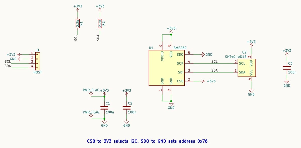
KiCad’s electrical rules check does not look at pull-ups. KiCad 9.0.9 reports 0 errors on this sheet, and 0 errors on a copy with R1 and R2 deleted, where the bus could never go high (both copies get the same single warning, for the BME280’s address pin strapped to the flagged ground). The AI PCB review page shows the same blind spot on a breakout.
A netlist does carry the answer, so a short script can check it. This one reads KiCad’s netlist export (kicad-cli sch export netlist --format kicadsexpr), finds every resistor from SDA or SCL to a supply rail, combines them and applies the two formulas. On the sheet above:
/SDA: R2 2.2k to +3V3 -> 2.20 kOhm, 1.32 mA to sink at VOL 0.4 V
  Standard-mode: rise time met up to 400 pF (spec limit 400 pF)
  Fast-mode: rise time met up to 161 pF
  Fast-mode Plus: rise time met up to 64 pF
On the copy with the pull-ups deleted, which ERC passed:
/SCL: NO PULL-UP. I2C is open-drain; this line never goes high on its own.
/SDA: NO PULL-UP. I2C is open-drain; this line never goes high on its own.
Run on the 4.7 kΩ BME280 breakout from the schematic-to-PCB guide, it reports 75 pF for 400 kHz and 251 pF for 100 kHz: right for that board on its own, short for a cable.
How PCBEditor handles I²C pull-ups
PCBEditor’s design check, which runs on the boards it designs, reports “I2C lines have no pull-up resistors” when an I²C pin’s net reaches another device and has no resistor to a supply. A bus pulled up on another board, through a connector, gets the warning too; read it as a reminder to confirm that board has them. When it builds a board from a description, it adds a 4.7 kΩ pull-up from each I²C line that has none to the chip’s own supply, and adds none when the chip has no supply connected to pull to.
The limit: the check knows a pull-up is there, not whether its value suits your bus. It does not know how long the cable is or how many modules will share the bus. 4.7 kΩ is right for a short on-board bus at 100 kHz and at 400 kHz up to 75 pF; for a cable or a crowded bus, name the value in your description and check it on the schematic before ordering.
Common questions
- What value pull-up resistor should I use for I2C at 3.3 V?
- Between 0.97 kΩ and tr / (0.8473 × Cb). For a short on-board bus at 400 kHz (under about 75 pF), 4.7 kΩ works; for a longer bus or a cable at 400 kHz, 2.2 kΩ covers up to 161 pF. At 100 kHz, 4.7 kΩ covers up to 251 pF. Never go below 0.97 kΩ for ordinary 3 mA devices.
- What is the formula for the I2C pull-up resistor?
- From NXP's I2C specification, section 7.1: Rp(min) = (VDD − VOL(max)) / IOL, with VOL(max) = 0.4 V and IOL = 3 mA for Standard-mode and Fast-mode (20 mA for Fast-mode Plus); Rp(max) = tr / (0.8473 × Cb), with tr = 1000 ns, 300 ns or 120 ns for 100 kHz, 400 kHz and 1 MHz. 0.8473 is ln(7/3), the time an RC edge takes from 0.3 VDD to 0.7 VDD.
- Is 4.7k or 10k better for I2C?
- Neither is right everywhere. At 3.3 V, 10 kΩ meets the 400 kHz rise time only below 35 pF and the 100 kHz one below 118 pF; 4.7 kΩ reaches 75 pF and 251 pF. 10 kΩ draws less current while a line is low, which matters on battery boards with a slow, short bus.
- Do I need pull-up resistors on every I2C device?
- No. One pair per bus, normally near the controller. Pull-ups on several modules add in parallel: four breakouts with 4.7 kΩ each make 1.18 kΩ, still inside the 3 mA limit at 3.3 V; a fifth makes 0.94 kΩ, which is too strong. At 5 V the limit is 1.7 kΩ, so two 4.7 kΩ pairs are the most.
- Can I use the ESP32's internal pull-ups for I2C?
- Only on a very short, slow bus. The ESP32-C3 datasheet gives 45 kΩ for the internal pull-up; with that, the 100 kHz rise time is met only below 26 pF, and every device pin may add up to 10 pF. Fit external resistors.
- Why does my I2C bus work only when I touch it or connect a scope probe?
- The line is marginal, and the extra capacitance changes the edge enough to tip it. Check the pull-up value against the wiring, keep SDA and SCL apart in a cable (the specification's order is SDA, VDD, VSS, SCL above 10 cm), slow the clock, and look at both lines on a scope with two probes.
Draw a two-sensor I²C board in PCBEditor
The editor opens with this board described in the chat box: a BME280 and an SHT40 on one bus with 2.2 kΩ pull-ups. Change it to your own parts; its design check reports an I²C line with no pull-up before any fab file is written.
Open the sensor board in the editor→Sources
Every resistance, capacitance and current on this page is calculated from the specification’s formulas and limits, or copied from the tool output shown. None is a bench measurement.
- NXP Semiconductors, UM10204 I²C-bus specification and user manual, Rev. 7.0, 1 October 2021: section 7.1 (pull-up resistor sizing, the 0.8473 × RC rise time, Rp(max) and Rp(min)), Table 10 (rise times, bus capacitance limits, VOL at 3 mA and 20 mA, pin capacitance), section 7.2 (operating above the bus capacitance limit), section 7.3 (series resistors) and section 7.5 (wiring pattern of the bus lines).
- Espressif, ESP32-C3 Series Datasheet v2.4: Table 5-4 DC characteristics (internal weak pull-up 45 kΩ) and section 4.2.1.3 I²C controller.
- Sensirion, SHT4x datasheet, Version 1, October 2020: Figure 1 typical application circuit (10 kΩ pull-ups, 100 nF) and Table 3 (pull-up and bus load limits).
- KiCad 9.0.9 kicad-cli sch erc and netlist export, run on the three schematics described on this page.
- Electrical Engineering Stack Exchange, question 772911, “I2C SDA line acts erratically, requiring touch to work” (November 2026), and its comments.