USB-C on a PCB: the two 5.1 kΩ resistors, and why boards get no power from a C-to-C cable
The most common USB-C mistake on a home-made board looks like this: it works from an old USB-A charger with an A-to-C cable, and gets nothing at all from a USB-C charger with a C-to-C cable. The second most common: power works both ways up, and USB data works only one way. Both come down to a few pins on the connector.
Last reviewed
Short answer
A USB-C charger keeps its 5 V off until it sees a device: a 5.1 kΩ resistor from a CC pin to ground. Fit one 5.1 kΩ from CC1 (A5) to ground and another from CC2 (B5) to ground, never one resistor for both. For USB 2.0 data, join D+ on A6 and B6, and D− on A7 and B7, right at the connector. With only these resistors the board gets 5 V, never more; higher voltages need a USB Power Delivery controller.
Why a C-to-C charger gives you nothing
A USB-C cable has the same plug at both ends, so the two ends have to work out which one supplies power. They do it on the CC (configuration channel) pins. The charger, the source, pulls CC up through a resistor called Rp. The device, the sink, pulls CC down to ground through 5.1 kΩ, called Rd. The charger watches the voltage on CC, and only when it sees that divider does it turn VBUS on. No Rd, no 5 V.
Old USB-A chargers hide the mistake. A USB-A port has 5 V on all the time, and an A-to-C cable carries the 56 kΩ pull-up in its USB-C plug, so a board with no CC resistors runs fine from it. Then someone plugs in a phone charger with a C-to-C cable, and the board is dead.
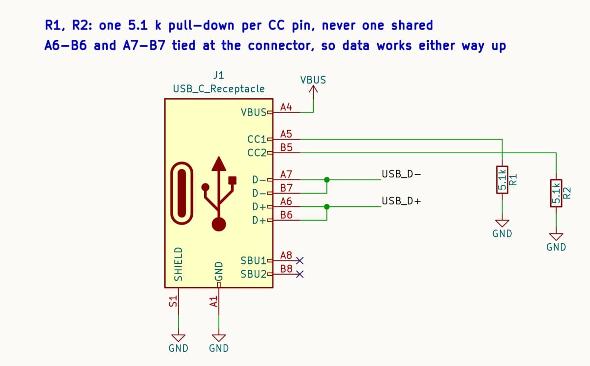
One resistor per CC pin, never shared
The receptacle has two CC pins, CC1 on A5 and CC2 on B5, because the plug can go in either way up. An ordinary cable connects one of them. An electronically marked (e-marked) cable, the kind sold for 5 A or for fast data, also puts its own 800 Ω to 1.2 kΩ resistor, Ra, on the other one. That is how the charger knows to power the chip inside the cable.
Tie CC1 and CC2 together through one 5.1 kΩ and, with an e-marked cable, the cable’s Ra lands in parallel with it: 5.1 kΩ and 1 kΩ in parallel is about 836 Ω. The charger reads that as Ra, not as a device, and keeps its 5 V off. That is what happened to the Raspberry Pi 4 in 2019: its two CC pins shared one resistor, and chargers with e-marked cables identified it as an audio adapter accessory and refused to power it.
Two resistors, not one
Data that works only one way up
A USB-C receptacle has D+ twice (A6 and B6) and D− twice (A7 and B7). A USB 2.0 plug has D+ and D− in one row only, so the plug orientation decides which pair is live: one way up it meets A6 and A7, turned over it meets B6 and B7. Wire only the A row to your microcontroller and USB data works one way up, while power works both ways. It looks like a flaky cable.
Join A6 to B6 and A7 to B7 right at the connector, then route one D+ and D− pair to the chip. ST’s application note on USB-C protection keeps the joining traces under 3.5 mm so the unused branch stays a short stub. The SBU pins are not used by USB 2.0 and can stay unconnected.
How much current you may draw
The charger’s pull-up says how much current it offers, and the voltage on your CC pin shows which one it is:
| Charger’s pull-up (to 5 V) | It offers | Voltage on your CC pin |
|---|---|---|
| 56 kΩ | Default USB power (500 mA on USB 2.0) | about 0.42 V |
| 22 kΩ | 1.5 A | about 0.94 V |
| 10 kΩ | 3.0 A | about 1.69 V |
A board that draws less than 500 mA can ignore this. One that needs more should read the CC voltage with an ADC or comparator, or use a sink controller that does it, before drawing 1.5 A or 3 A. Either way the voltage stays 5 V: a charger offers 9, 15 or 20 V only after a USB Power Delivery negotiation, which takes a PD controller, not resistors.
The checklist
- CC1 (A5) to ground through 5.1 kΩ, and CC2 (B5) to ground through its own 5.1 kΩ.
- Every VBUS pin (A4, A9, B4, B9) on the supply, and every GND pin (A1, A12, B1, B12) on ground.
- D+ on A6 and B6 joined, D− on A7 and B7 joined, at the connector, for USB 2.0 data.
- SBU1 and SBU2 unconnected unless you know you need them.
- A power-only receptacle still gets both CC resistors.
- Test with a USB-C charger and a C-to-C cable, both ways up, and with an e-marked cable if you have one. An A-to-C cable proves nothing about CC.
How PCBEditor checks it
Boards PCBEditor generates are checked for this. A USB-C receptacle that powers the board needs its own 5.1 kΩ to ground on each CC contact, and a CC pin left open, tied straight to ground or to a supply, given the wrong value, or sharing one resistor with the other CC pin is reported as an error. Generated boards have come back with CC “pull-downs” drawn as 0 Ω, CC pins wired to microcontroller GPIOs and a CC pin used as the supply, which is why the check exists. If you draw the schematic yourself, the circuit diagram maker shows the connector’s pin names, so you can check each line of the list above against it.
Common questions
- Why does my USB-C board work with an A-to-C cable but not a C-to-C cable?
- A USB-A port has 5 V on all the time, and an A-to-C cable carries a 56 kΩ pull-up inside its USB-C plug, so the board gets power with or without CC resistors. A USB-C charger turns its 5 V on only after it sees a 5.1 kΩ pull-down on a CC pin. A board without them looks like nothing is plugged in.
- What value are the USB-C CC resistors?
- On a device that takes power (a sink), 5.1 kΩ from CC1 to ground and 5.1 kΩ from CC2 to ground. A charger or host (a source) uses pull-ups instead: 56 kΩ, 22 kΩ or 10 kΩ to 5 V, which also tell the device how much current it may draw.
- Can I use one 5.1 kΩ resistor for both CC pins?
- No. With an electronically marked cable, the cable's own 800 Ω to 1.2 kΩ resistor ends up in parallel with your 5.1 kΩ, and the charger reads the result as a cable or an audio adapter, not a device. The Raspberry Pi 4 shipped with this mistake in 2019, and some chargers refused to power it.
- Why does USB data only work when the plug is one way up?
- A USB 2.0 plug has its D+ and D− contacts in one row only. Turned over, they land on the receptacle's other row, B6 and B7 instead of A6 and A7. If only one row is wired to the microcontroller, data works one way up and power works both ways.
- Can I get 9 V, 12 V or 20 V from USB-C with resistors?
- No. A charger starts at 5 V and goes higher only after a USB Power Delivery negotiation. For more than 5 V, fit a USB PD sink controller.
- Do power-only USB-C connectors need CC resistors?
- Yes. Six-pin and other power-only receptacles keep CC1 and CC2 because the charger still needs to see a device before it turns 5 V on.
Start a USB-C board with the resistors already right
The editor opens with a USB-C power board described in the chat box: 5.1 kΩ on each CC pin, both data rows joined. Change it to your circuit.
Open the USB-C board in the editor→Sources
CC voltages in the table are computed for a 5.0 V pull-up and a 5.1 kΩ pull-down; the specification gives a window around each.
- USB Type-C Cable and Connector Specification (USB Implementers Forum): the Configuration Channel and its Rp, Rd and Ra terminations.
- Infineon knowledge base, Termination resistors required for the USB Type-C connector: Rd 5.1 kΩ; Rp 56 kΩ, 22 kΩ and 10 kΩ to 4.75–5.5 V; Ra 800 Ω to 1.2 kΩ.
- STMicroelectronics application note AN4871 (DocID029326, September 2016): A6 with B6 and A7 with B7 may be shorted near the receptacle, stub under 3.5 mm; a plug has no B6/B7 contacts.
- Chromium OS, USB Type-C cable and adapter tips and tricks: legacy USB-A to USB-C cables use a 56 kΩ Rp.
- TechCrunch (9 July 2019) and The Register (10 July 2019) on the Raspberry Pi 4, whose two CC pins share one 5.1 kΩ; Eben Upton’s statement on chargers with e-marked cables.
- Hackaday, All About USB-C: Resistors and Emarkers (January 2023): a shared 5.1 kΩ in parallel with a cable’s 1 kΩ Ra is about 840 Ω.