3.3 V from a LiPo cell: dropout, buck-boost, and what actually works
A single LiPo cell and a 3.3 V regulator is the most common battery circuit on a hobby board, and it has a catch: the cell spends part of its charge too close to 3.3 V for the regulator to hold. The board works on the bench, then browns out or resets near the end of the charge, usually during a radio burst. Here is the arithmetic, with real datasheet numbers, and the four ways out.
Last reviewed
Short answer
A LiPo cell gives about 4.2 V full, 3.7 V nominal and 3.0 V empty. A 3.3 V LDO needs its input to stay above 3.3 V plus its dropout. The AP2112K-3.3 needs up to 3.5 V at 300 mA and up to 3.7 V at 600 mA. Below that it does not shut off: the output follows the cell down. That is fine if every part on the rail runs at 3.0 V. If they don’t, or you need the whole charge, use a buck-boost converter such as the TPS63001, which holds 3.3 V from 1.8 V to 5.5 V in.
The cell’s range against the rail
A LiPo (or any lithium-ion) cell charges to 4.2 V, sits around 3.7 V for most of its discharge, and is considered empty at about 3.0 V, where a protection circuit usually cuts it off. A 3.3 V rail sits inside that range, near the bottom. While the cell is full there is almost a volt to spare; towards the end there is nothing.
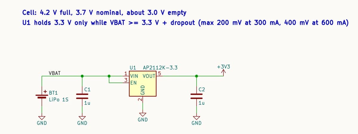
Dropout, in numbers
A linear regulator can only take voltage away. Its dropout is the smallest gap between input and output at which it still regulates, and it grows with load current. For the AP2112K-3.3, a common choice on single-cell boards, the datasheet gives:
| Load | Dropout, typical | Dropout, maximum | Cell must stay above (maximum) |
|---|---|---|---|
| 10 mA | 5 mV | 8 mV | 3.31 V |
| 300 mA | 125 mV | 200 mV | 3.50 V |
| 600 mA | 250 mV | 400 mV | 3.70 V |
At 600 mA, the regulator’s full rating, the worst case needs 3.7 V in: the cell’s nominal voltage. At light load it regulates almost all the way down to 3.3 V. Below those points the regulator does not switch off. It goes into dropout and its output follows the cell, a little below it. Whether that matters depends on the parts on the rail: many 3.3 V microcontrollers and modules are rated down to 3.0 V, so check the minimum supply voltage in each datasheet.
Why boards reset near the end of the charge
Average current is not the problem; peaks are. A Wi-Fi radio draws short bursts of several hundred milliamps while it transmits. The dropout is largest at exactly those moments, the cell’s own internal resistance pulls its voltage down at the same time, and near the end of the charge the two together take the rail below what the chip accepts. Its brownout detector resets it, and the symptom looks like a firmware bug: the board reboots whenever it tries to connect.
Bench supplies hide it
Four ways to get 3.3 V
- A low-dropout regulator, and accept the tail. Simplest and quietest. Choose one whose dropout at your peak current is small, put bulk capacitance at the load, and set the firmware’s low-battery cut-off above the point where the rail starts to sag.
- A buck converter with a 100% duty cycle mode. The TPS62743 (2.15–5.5 V in, 300 mA) switches efficiently while the cell is full, then holds its switch on and passes the cell through as it nears 3.3 V, much like an LDO in dropout. Better battery life than an LDO at high load, the same tail.
- A buck-boost converter. The TPS63001 takes 1.8–5.5 V and holds 3.3 V across the whole cell, stepping down while the cell is above 3.3 V and up below it. Up to 800 mA in boost mode. It costs an inductor, a few more parts and some switching noise, and it is the only option here that uses the whole charge at a steady 3.3 V.
- A lower rail. If every part on the rail runs at 3.0 V, a 3.0 V regulator keeps regulating for longer down the cell, for the same parts count as option 1.
Check the input range first
Before dropout, check that the regulator runs from one cell at all. Many popular buck converters are rated for 4.5 V input and up, which a single cell never reaches: the XL1509-3.3, for example, is rated 4.5–40 V. In the session in our MCP guide, exactly that part was offered as one of two substitute regulators for a single-cell board. The session took the other, a step-down converter that cannot hold 3.3 V as the cell runs down, and the board was routed and passed the design-rule check. A design-rule check measures copper; it does not read the regulator’s datasheet. Take the input range from the manufacturer’s datasheet, not a parts summary.
Running the board while it charges
With a simple charger such as the MCP73831 and the regulator wired to the cell, the board draws from the charger’s output while it charges. The charger cannot tell your load from the cell. It ends the charge when its current falls to a set fraction of the programmed current, and a load that draws more than that keeps the current from ever falling far enough, so the cell can sit at 4.2 V instead of finishing. Microchip’s AN1149 shows the fix: a load-sharing path with a P-channel MOSFET, a Schottky diode and a resistor, which runs the board from USB while it is plugged in and from the cell when it is not.
Common questions
- Can I use an LDO to get 3.3 V from a LiPo?
- Yes, with a low-dropout one, as long as you accept that it stops regulating near the end of the charge. An AP2112K-3.3 holds 3.3 V while the cell stays above about 3.5 V at 300 mA (worst case). Below that its output follows the cell down, which most 3.0 V-capable parts tolerate.
- What is the dropout of the AP2112K-3.3?
- From Diodes’ datasheet: 5 mV typical (8 mV maximum) at 10 mA, 125 mV (200 mV) at 300 mA, and 250 mV (400 mV) at 600 mA.
- Why does my ESP32 reset on battery but not on USB?
- Wi-Fi transmit bursts draw current peaks, and an LDO’s dropout is largest at its peak current. Near the end of the charge the cell is low and the dropout is high at the same moment, the rail dips, and the brownout detector resets the chip. Add bulk capacitance at the module, raise your low-battery cut-off, or use a buck-boost converter.
- Do I need a buck-boost converter for a LiPo?
- Only if a part on the 3.3 V rail cannot run below 3.3 V, or you need the last part of the cell’s charge. A buck-boost such as the TPS63001 holds 3.3 V from 1.8 V to 5.5 V in, at the cost of an inductor, more parts and switching noise.
- Can I power a 3.3 V chip straight from a LiPo?
- Not a chip rated to 3.6 V, because a full cell gives 4.2 V. Check the absolute maximum supply voltage in its datasheet; some low-voltage parts accept the whole cell range, most 3.3 V microcontrollers do not.
Start a battery board with the supply range in the description
The editor opens with a single-cell board described in the chat box, battery range included. Change it to your circuit.
Open the battery board in the editor→Sources
Cell voltages are the usual single-cell LiPo values; use the figures from your own cell’s datasheet.
- Diodes Incorporated, AP2112 datasheet (DS39724 Rev. 2, June 2017): 3.3 V version dropout 5/8 mV at 10 mA, 125/200 mV at 300 mA, 250/400 mV at 600 mA (typical/maximum); input 2.5–6.0 V.
- Texas Instruments, TPS6300x datasheet (SLVS520C): input 1.8–5.5 V, TPS63001 fixed 3.3 V output, up to 1200 mA in step-down mode (VIN 3.6–5.5 V) and 800 mA in boost mode (VIN above 2.4 V).
- Texas Instruments, TPS62743 datasheet (SLVSCQ0B): input 2.15–5.5 V, 300 mA, 100% duty cycle mode in which the output follows the input.
- XLSEMI XL1509 datasheet: input 4.5–40 V.
- Microchip application note AN1149: a load-sharing power path for its stand-alone Li-ion charge management controllers.