ESP32-C3 pinout: every GPIO, every ESP32-C3-MINI-1 pin, and the two pins that decide whether it boots
The ESP32-C3 is Espressif’s small single-core RISC-V chip with Wi-Fi and Bluetooth LE, and it sits on a long list of boards, from Espressif’s own ESP32-C3-MINI-1 module to the XIAO ESP32C3 and the Super Mini. This page gives each of its 22 GPIOs and every pin of the MINI-1, drawn on Espressif’s own KiCad footprint, and the details that trip up new boards: the boot mode needs two pins, not one, and several GPIOs carry the USB, the JTAG or the UART0 you flash through.
Last reviewed
Short answer
The ESP32-C3 has 22 GPIOs, GPIO0 to GPIO21. GPIO11 to GPIO17 belong to the flash, so the ESP32-C3-MINI-1 brings out 15 of them on 53 pads. The boot button goes on GPIO9 (pad 23): GPIO9 low at reset enters download mode, but only while GPIO8 (pad 22) is high, and GPIO8 floats, so give it a pull-up. USB is GPIO18 (D−) and GPIO19 (D+); UART0 is GPIO21 (TX) and GPIO20 (RX). ADC1 is on GPIO0 to GPIO4. I²C and SPI can go on any free GPIO. Feed 3V3 with at least 0.5 A.
The ESP32-C3-MINI-1 footprint
The MINI-1 is 13.2 × 16.6 × 2.4 mm with pads on a 0.8 mm pitch. Pads 1 to 11 run down the left, 12 to 24 along the bottom, 25 to 35 up the right, and 36 to 48 across the top, just below the antenna, all ground. Pad 49 in the middle is a ground pad made of nine squares, and pads 50 to 53 are the corner grounds. Many of the pads are not connected: the module only brings out the GPIOs the chip has free.
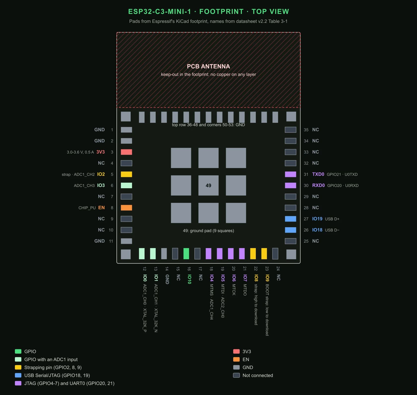
All 22 GPIOs and what each one is for
The ESP32-C3 chip is a QFN32, 5 × 5 mm. This table follows its GPIO numbers, which are also the numbers you use in code, and gives the MINI-1 pad for each one. “Free” means Espressif lists no restriction on it.
| GPIO | MINI-1 pad | Fixed functions | Use with care because |
|---|---|---|---|
| GPIO0 | 12 | ADC1_CH0, XTAL_32K_P | Free, unless you fit the optional 32.768 kHz crystal |
| GPIO1 | 13 | ADC1_CH1, XTAL_32K_N | Free, unless you fit the optional 32.768 kHz crystal |
| GPIO2 | 5 | ADC1_CH2, FSPIQ | Strapping pin. Espressif recommends a pull-up |
| GPIO3 | 6 | ADC1_CH3 | Free |
| GPIO4 | 18 | ADC1_CH4, FSPIHD, MTMS (JTAG) | JTAG pin; free if you debug over USB |
| GPIO5 | 19 | ADC2_CH0, FSPIWP, MTDI (JTAG) | JTAG pin. Its ADC channel is ADC2: not calibrated |
| GPIO6 | 20 | FSPICLK, MTCK (JTAG) | JTAG pin; free if you debug over USB |
| GPIO7 | 21 | FSPID, MTDO (JTAG) | JTAG pin; free if you debug over USB |
| GPIO8 | 22 | GPIO8 | Strapping pin: must be high to enter download mode, and it floats at reset |
| GPIO9 | 23 | GPIO9 | Strapping pin: the BOOT button. Weak pull-up; low at reset enters download mode |
| GPIO10 | 16 | FSPICS0 | Free |
| GPIO11 | None | VDD_SPI | The flash supply pin. Not on the MINI-1 |
| GPIO12 to GPIO17 | None | SPIHD, SPIWP, SPICS0, SPICLK, SPID, SPIQ | The flash interface. Not on the MINI-1 |
| GPIO18 | 26 | USB D− | USB Serial/JTAG by default. Driven high for about 50 µs at power-up |
| GPIO19 | 27 | USB D+ | USB Serial/JTAG by default |
| GPIO20 | 30 (RXD0) | U0RXD | UART0 receive: flashing and the boot log |
| GPIO21 | 31 (TXD0) | U0TXD | UART0 transmit: flashing and the boot log |
UART1, I²C, I²S, the TWAI (CAN) controller and the LED PWM outputs have no fixed pins: the GPIO matrix routes them to any free GPIO. The FSPI names are the pins the general-purpose SPI reaches directly through the IO MUX; through the GPIO matrix it can use other pins too.
All 53 MINI-1 pins
Names and functions from Table 3-1 of the module datasheet.
| Pad | Name | Function |
|---|---|---|
| 1, 2 | GND | Ground |
| 3 | 3V3 | Supply, 3.0 to 3.6 V; the supply must deliver at least 0.5 A |
| 4 | NC | Not connected |
| 5 | IO2 | GPIO2, ADC1_CH2, FSPIQ. Strapping pin |
| 6 | IO3 | GPIO3, ADC1_CH3 |
| 7 | NC | Not connected |
| 8 | EN | High enables the chip, low powers it off. Do not leave it floating |
| 9, 10 | NC | Not connected |
| 11 | GND | Ground |
| 12 | IO0 | GPIO0, ADC1_CH0, XTAL_32K_P |
| 13 | IO1 | GPIO1, ADC1_CH1, XTAL_32K_N |
| 14 | GND | Ground |
| 15 | NC | Not connected |
| 16 | IO10 | GPIO10, FSPICS0 |
| 17 | NC | Not connected |
| 18 | IO4 | GPIO4, ADC1_CH4, FSPIHD, MTMS |
| 19 | IO5 | GPIO5, ADC2_CH0, FSPIWP, MTDI |
| 20 | IO6 | GPIO6, FSPICLK, MTCK |
| 21 | IO7 | GPIO7, FSPID, MTDO |
| 22 | IO8 | GPIO8. Strapping pin |
| 23 | IO9 | GPIO9. Strapping pin (boot mode) |
| 24, 25 | NC | Not connected |
| 26 | IO18 | GPIO18, USB_D− |
| 27 | IO19 | GPIO19, USB_D+ |
| 28, 29 | NC | Not connected |
| 30 | RXD0 | GPIO20, U0RXD |
| 31 | TXD0 | GPIO21, U0TXD |
| 32 to 35 | NC | Not connected |
| 36 to 53 | GND | Ground: the row under the antenna end (36 to 48), the centre pad (49) and the four corners (50 to 53) |
| Module | Flash in the chip | Ambient |
|---|---|---|
| ESP32-C3-MINI-1-N4X | 4 MB | −40 to 85 °C |
| ESP32-C3-MINI-1-H4X | 4 MB | −40 to 105 °C |
| ESP32-C3-MINI-1-H8X | 8 MB | −40 to 105 °C |
| ESP32-C3-MINI-1U-N4X | 4 MB | −40 to 85 °C |
| ESP32-C3-MINI-1U-H4X | 4 MB | −40 to 105 °C |
Those are the variants Espressif lists as current; the older N4, H4 and H4-AZ are not recommended for new designs. The MINI-1U is 13.2 × 12.5 × 2.4 mm, has a connector for an external antenna in place of the PCB antenna, and uses the same pads with no antenna keep-out.
Strapping pins: GPIO9 and GPIO8
Three pins are read when EN goes high and latched until power-down. Espressif asks for them to hold their level for at least 3 ms after EN rises; after that they work as normal GPIOs.
| Pin | Default at reset | What it does |
|---|---|---|
| GPIO9 (pad 23) | Weak pull-up (1) | Boot mode. High: boot from flash. Low with GPIO8 high: download mode over UART0 or USB |
| GPIO8 (pad 22) | Floating | Must be high for download mode. With GPIO9 high it does not matter for booting |
| GPIO2 (pad 5) | Floating | Does not select the boot mode, but Espressif recommends pulling it up because of glitches |
A BOOT button on GPIO9 is not enough: GPIO8 has to be high
With the Arduino core’s defaults for a generic ESP32-C3 board, SDA is GPIO8 and SCL is GPIO9, so an I²C bus sits on both boot pins. Its pull-up resistors give the right levels at reset, but a sensor that holds SCL low while the chip starts can send it into download mode. On your own board, put I²C on other free GPIOs.
USB on GPIO18 and GPIO19
GPIO18 (D−) and GPIO19 (D+) connect to the USB Serial/JTAG controller by default: a USB 2.0 full-speed port that gives you a serial console, flashing and JTAG debugging with no USB-to-UART chip. Wire them straight to a USB-C receptacle as a pair, and leave room for 22 to 33 Ω series resistors and small capacitors to ground (fitted only if needed) close to the module, as Espressif suggests. A USB-C receptacle also needs its own 5.1 kΩ resistor on CC1 and on CC2: USB-C CC resistors explains why.
Once firmware is running, tools can usually reset the chip into download mode over this port without touching the buttons. That stops working if the application turns the USB PHY off, uses the port as a USB host or device, or gives GPIO18 and GPIO19 to another peripheral; then you need the BOOT button. Espressif recommends keeping control of the strapping pins for that reason, and keeping the UART0 download interface too.
ADC pins
The ESP32-C3 has two 12-bit SAR ADCs. ADC1 reads GPIO0 to GPIO4 (channels 0 to 4) and is factory-calibrated. ADC2 has one channel, on GPIO5, is not calibrated, and does not work on some chip revisions, so Espressif recommends ADC1. The calibrated ranges from the hardware design guidelines:
- Attenuation 0: 0 to 750 mV, total error ±10 mV.
- Attenuation 1: 0 to 1,050 mV, ±10 mV.
- Attenuation 2: 0 to 1,300 mV, ±10 mV.
- Attenuation 3: 0 to 2,500 mV, ±35 mV.
A battery voltage above 2.5 V needs a divider, and Espressif suggests a 0.1 µF capacitor from each ADC pin to ground. The ESP32 battery charger circuit sizes that divider for a Li-ion cell.
XIAO ESP32C3 and Super Mini pins
Small boards print their own names on the pins. The Arduino core defines them in each board’s variant file; here are the two boards people ask about most:
| Function | XIAO ESP32C3 | ESP32-C3 Super Mini |
|---|---|---|
| Analog inputs | A0 to A2 = GPIO2 to GPIO4 | A0 to A5 = GPIO0 to GPIO5 |
| I²C | SDA GPIO6 (D4), SCL GPIO7 (D5) | SDA GPIO8, SCL GPIO9 |
| SPI | SCK GPIO8 (D8), MISO GPIO9 (D9), MOSI GPIO10 (D10) | SCK GPIO4, MISO GPIO5, MOSI GPIO6, SS GPIO7 |
| UART0 | TX GPIO21 (D6), RX GPIO20 (D7) | TX GPIO21, RX GPIO20 |
| Built-in LED | None in the variant | GPIO8 |
The XIAO’s D0 to D10 are GPIO2, 3, 4, 5, 6, 7, 21, 20, 8, 9 and 10. That puts D8 and D9 on the two boot pins: a part that holds D9 low at power-up can send the board into download mode. The Super Mini’s Arduino variant uses plain GPIO numbers and puts its LED on GPIO8, one of the boot pins, so keep that pin free of anything that pulls it low at reset.
What your board needs
- Power: 3.3 V on pad 3 from a regulator that can deliver at least 0.5 A, with 10 µF and 0.1 µF at the module as in Espressif’s peripheral schematic.
- EN: never floating. An RC delay of 10 kΩ to 3V3 and 1 µF to ground lets the supply settle before the chip starts; add a reset button from EN to ground.
- Boot: a button from GPIO9 to ground, a pull-up on GPIO8, and a pull-up on GPIO2 as Espressif recommends.
- Flashing: USB-C to GPIO18 and GPIO19, or a USB-to-UART bridge to TXD0 and RXD0 (pads 31 and 30). Espressif recommends a 499 Ω series resistor on U0TXD to suppress harmonics.
- Antenna: put the antenna end at the edge of the board, ideally hanging past it, with no copper on any layer under it, and dense ground vias on the board next to it. Espressif recommends at least 15 mm of clearance around the antenna inside the enclosure.
- Ground: soldering the centre pad (49) is optional and helps with heat. Do not over-paste it, or the module sits too high for the edge pads to wet.
The ESP32 PCB design guide walks through the same support circuit on a finished board, from the regulator to the antenna keep-out.
The ESP32-C3 in PCBEditor
PCBEditor’s part library carries the ESP32-C3-MINI-1 with Espressif’s own KiCad footprint, the same pads drawn in the figure above, beside the bare ESP32-C3 and the WROOM-02. The MINI-1’s antenna keep-out becomes a keep-out on your board that moves with the module: the copper pour, the router and the rules check keep copper out of it, and the KiCad export writes it as a rule area.
When PCBEditor draws the schematic for an ESP32-C3 board, it gives the chip a way to load its firmware: the USB port when GPIO18 and GPIO19 are wired to one, otherwise a programming header on UART0 (GPIO21 and GPIO20) with the boot line on GPIO9. It treats GPIO8 as a strapping pin that must be high: if nothing else on the board holds it, it adds a 10 kΩ pull-up to 3.3 V, and its electrical check reports a floating GPIO8 as an error.
Common questions
- How many GPIOs does the ESP32-C3 have?
- 22, numbered GPIO0 to GPIO21. GPIO11 is the flash supply pin by default and GPIO12 to GPIO17 are the flash interface, so the ESP32-C3-MINI-1 brings out 15: GPIO0 to GPIO10 and GPIO18 to GPIO21. The ESP32-C3FH4X chip, Espressif's recommended variant with 4 MB of flash in the package, has 16 because its flash pins are not bonded out.
- Which pin is the BOOT pin on the ESP32-C3?
- GPIO9 (pad 23 on the ESP32-C3-MINI-1). It has a weak pull-up, so the chip boots from flash when nothing drives it. Holding it low at reset enters download mode, but only if GPIO8 is high at the same moment. A button from GPIO9 to ground plus a pull-up on GPIO8 is the whole boot circuit.
- Why won't my ESP32-C3 enter download mode?
- Check GPIO8 first. Download mode needs GPIO8 high and GPIO9 low at reset, and GPIO8 has no pull of its own, so a board that leaves it floating or loads it low may never enter download mode. If you normally flash over USB without buttons, the firmware may have disabled the USB PHY or reused GPIO18 and GPIO19; then hold BOOT (GPIO9 low) while you reset.
- Which ESP32-C3 pins are SDA and SCL?
- There are no fixed I²C pins: the GPIO matrix can route I²C to any free GPIO. The Arduino core's generic ESP32-C3 board uses GPIO8 for SDA and GPIO9 for SCL, both strapping pins, and the XIAO ESP32C3 uses GPIO6 and GPIO7. If you choose your own, avoid the strapping pins and GPIO18 to GPIO21.
- Which ESP32-C3 pins can read analog voltages?
- GPIO0 to GPIO4 on ADC1, which is factory-calibrated, and GPIO5 on ADC2, which is not calibrated and does not work on some chip revisions. Espressif recommends ADC1. With the highest attenuation the calibrated range is 0 to 2,500 mV with a total error of ±35 mV.
- Can I use GPIO18 and GPIO19 as normal GPIOs?
- Yes, once the firmware reconfigures them, but you lose the USB Serial/JTAG port, and with it flashing and the console over USB. GPIO18 is also driven high for about 50 µs at power-up, so do not put anything on it that must stay low while the chip starts.
Build an ESP32-C3 board in PCBEditor
The editor opens with this board described in the chat box. PCBEditor draws the schematic with GPIO9 as the boot pin and GPIO8 held high, gives the chip a way to load its firmware, and places the module with its antenna keep-out.
Start this board→Sources
The board pin names in the XIAO and Super Mini table are the Arduino core's names for those boards; check the silkscreen of the board you have.
- Espressif, ESP32-C3 Series Datasheet v2.4: Table 1-1 (series comparison), Table 2-1 (pin overview), Table 2-2 (power-up glitches), Sections 2.3.3 and 2.3.4 (GPIO restrictions and peripheral pin assignment), IO MUX table, Section 4.2.2.1 (SAR ADC).
- Espressif, ESP32-C3-MINI-1 & ESP32-C3-MINI-1U Datasheet v2.2: Tables 1-1 and 1-2 (variants and sizes), Table 3-1 (pin definitions), Chapter 4 (boot configurations), Table 6-2 (recommended operating conditions), Figure 9-1 (peripheral schematic).
- Espressif, ESP32-C3 Hardware Design Guidelines, release master (revision history to v1.8): UART, strapping pins, ADC, USB, module placement and antenna clearance, download guidelines.
- arduino-esp32 (github.com/espressif/arduino-esp32), variants esp32c3, XIAO_ESP32C3 and nologo_esp32c3_super_mini, pins_arduino.h, read 8 November 2026.
- Espressif KiCad libraries (github.com/espressif/kicad-libraries), footprint Espressif.pretty/ESP32-C3-MINI-1 and symbol ESP32-C3-MINI-1, CC-BY-SA 4.0: pad positions for the figure; symbol pin names checked against Table 3-1 with no mismatch.