Flyback diode: which way it goes, which diode to use, and why it slows a relay
Every relay, solenoid, motor and fan is a coil, and a coil does not let its current stop. Switch it off with a transistor and the coil drives the transistor’s output as high as it takes to keep the current flowing: tens or hundreds of volts, for a fraction of a millisecond, every time. A flyback diode gives that current somewhere to go. This page shows which way round it goes, which part to use, and the catch most guides skip: the plain diode makes a relay let go late. The numbers come from ngspice runs and a KiCad schematic, both shown below.
Last reviewed
Short answer
Put the diode across the coil, not across the switch, with its cathode (the striped end) on the supply side and its anode on the side the transistor switches. It is reverse-biased while the coil is on and conducts only when the switch opens. Rate it for at least the supply voltage and the coil’s on current: a 1N4148 covers a small relay coil, a 1N4007 a solenoid or motor up to about 1 A, and a Schottky is the choice when the load is switched by PWM. A plain diode lets the current die away slowly, so a relay releases late; where that matters, put a Zener in series with the diode and use a transistor rated above the supply plus the Zener voltage.
What a coil does when you switch it off
A coil stores energy in its magnetic field, ½ L I². For a small 12 V solenoid valve modelled as 24 Ω and 50 mH, the 0.5 A it draws stores 6.25 mJ. When the transistor opens, that current has nowhere to go, and the coil raises its own voltage, V = L × di/dt, until something conducts. With nothing across the coil, the only thing left is the transistor itself: its drain climbs until the MOSFET breaks down (avalanches) and the energy is dumped inside it.
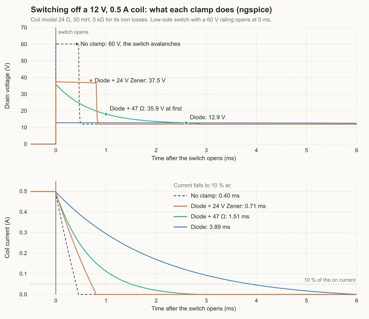
The simulation below does exactly that with a 60 V MOSFET on a 12 V supply: the drain jumps to 60.2 V and the switch absorbs 6.4 mJ every time it turns off. Unless the datasheet rates the part for repetitive avalanche, that is outside its rating on every switch-off, and a bipolar transistor simply breaks down. The spike also rides on the ground and supply wiring, which is how a solenoid or motor resets a microcontroller or drops a USB connection on the same board.
Which way round the diode goes
The diode goes across the load, and it must be reverse-biased while the load is on. That fixes its direction:
- Low-side switch (an N-MOSFET or NPN transistor pulls the bottom of the coil to ground, the usual microcontroller circuit): cathode to the positive supply, anode to the drain or collector.
- High-side switch (a P-MOSFET or high-side driver feeds the top of the coil, the bottom goes to ground): cathode to the switched output, anode to ground.
When the switch opens, the coil’s current keeps flowing in the same direction and turns round through the diode, back into the top of the coil. The switched node sits one diode drop above the supply, 12.9 V in the simulation, until the energy is spent in the coil’s resistance and the diode.
Two ways to get it wrong that a schematic check will not flag
Which diode: voltage, current and speed
Three numbers decide it:
- Reverse voltage: the diode sees the supply voltage, reversed, whenever the coil is on. Pick a rating comfortably above it. A 1N4148 is rated 100 V and a 1N4007 1000 V, so both clear 12 V and 24 V coils with room to spare.
- Current: at the instant the switch opens, the diode carries the full on current of the coil, then less. Use a diode rated for at least that current. A 12 V relay coil draws tens of milliamps, inside a 1N4148’s rating; a solenoid valve or small motor takes a 1 A rectifier such as the 1N4007; bigger loads need a bigger diode, not a smaller one.
- Speed: if the load is only switched on and off, any rectifier is fast enough. If it is driven by PWM (motor speed control, a solenoid’s holding current), the diode conducts every cycle and is turned off hard each time the transistor turns back on. A slow rectifier like the 1N4007 conducts backwards for a moment, and the transistor takes a current spike every cycle. Use a Schottky or an ultrafast diode rated for the load current.
The transistor’s rating follows from the clamp you choose: with a plain diode the drain never goes much above the supply, so a 30 V MOSFET is fine on 12 V. With a Zener or resistor in the clamp it goes higher, as the next section shows.
The catch: a plain diode slows release
A diode keeps the switched node low by letting the coil’s current circulate. That is also why the current takes so long to stop: the only thing pushing against it is the coil’s own resistance and one diode drop. It dies away with the coil’s time constant, L / R (2.1 ms for this model), and reaches 10 % after 3.89 ms. A relay’s contacts open only when the current has fallen far enough, so a relay with a plain diode releases late and its contacts part slowly. TE Connectivity’s application note on coil suppression makes the same point, and that slow parting is where arcing wears contacts.
The fix is to let the node rise further during the turn-off, so the current is pushed down faster. All five runs, same coil, same switch:
| Clamp | Peak at the drain | Current to 10 % | Energy into the switch | What it asks of the parts |
|---|---|---|---|---|
| None | 60.2 V (the switch avalanches) | 0.40 ms | 6.4 mJ every turn-off | A switch that survives avalanche, every time |
| Diode | 12.9 V | 3.89 ms | 0 | Nothing; slowest release |
| Diode + 47 Ω | 35.9 V, falling | 1.51 ms | 0 | Switch rated above 12 V + 0.5 A × 47 Ω |
| Diode + 24 V Zener | 37.5 V, flat | 0.71 ms | 0 | Switch rated above about 37 V |
| TVS across the switch (36.7 V) | 37.1 V, flat | 0.71 ms | 0 (the TVS takes it) | TVS rated for the pulse energy and how often it comes |
The diode with a 24 V Zener stops the current 5.5 times faster than the diode alone (0.71 ms against 3.89 ms), nearly as fast as no clamp at all, while keeping the energy out of the transistor. The price is the higher drain voltage: about the supply plus the Zener voltage plus a diode drop, 37.5 V here, so the transistor needs a rating above that with margin. A 30 V MOSFET that was fine with the plain diode is not. A resistor in series with the diode is a cheaper middle ground: the peak is the supply plus the coil current times the resistance, and the current falls with a shorter time constant, L / (R + Rs).
A TVS diode from the drain to ground does the same job as the Zener from the other side: the node clamps at the TVS breakdown and the current stops as fast. The difference is where the energy goes. The diode and Zener recirculate the current through the coil; the TVS takes a pulse of energy every switch-off, so check its pulse rating and its average power at your switching rate.
Relays, solenoids and motors
- Relays: a bare relay always needs a diode; size it for the coil current, never the contact rating printed on the relay. Relay modules for Arduino and similar boards usually carry the transistor and the diode already. Where release time matters (contacts switching a heavy or inductive load), use the diode and Zener.
- Solenoids and valves: they draw far more than a relay coil, so the diode is a 1 A part or bigger. A valve on a long cable is still clamped at the board, next to the transistor; a second diode at the valve keeps the cable from radiating the edge.
- DC motors switched one way: a diode across the motor, as for a solenoid, and a Schottky if you control the speed with PWM. Size the diode for the motor’s stall current, not its running current: that is what flows if the motor is switched off while stuck.
- Motors that reverse: no diode across the motor. In an H-bridge the freewheeling path is a diode across each switch, which the MOSFET body diodes or the driver IC provide; check the driver’s datasheet before adding any.
- AC coils: no diode at all, since it would conduct on every other half cycle. Use an RC snubber, or a MOV or bidirectional TVS sized for the line voltage.
Where it goes on the board
At the instant the transistor opens, the coil current has to move from the transistor to the diode in nanoseconds. Any wiring between them is inductance of its own, and it kicks the drain even with a perfect diode. Put the diode next to the transistor and the load’s connector, with the supply’s local capacitor close by, so the loop the current jumps between is small. Route the diode’s path for the full coil current; the trace width guide gives widths for a solenoid’s current.
What KiCad’s ERC sees, and a netlist check
This is the board from the CTA below, drawn in KiCad 9: block A is the solenoid valve with its plain 1N4007; block B is the relay with a 1N4148W and a 24 V Zener in series across the coil, on a 60 V 2N7002 because of the higher clamp. Check that the MOSFET you choose is fully on at your logic voltage, from the on-resistance its datasheet gives at that gate voltage.
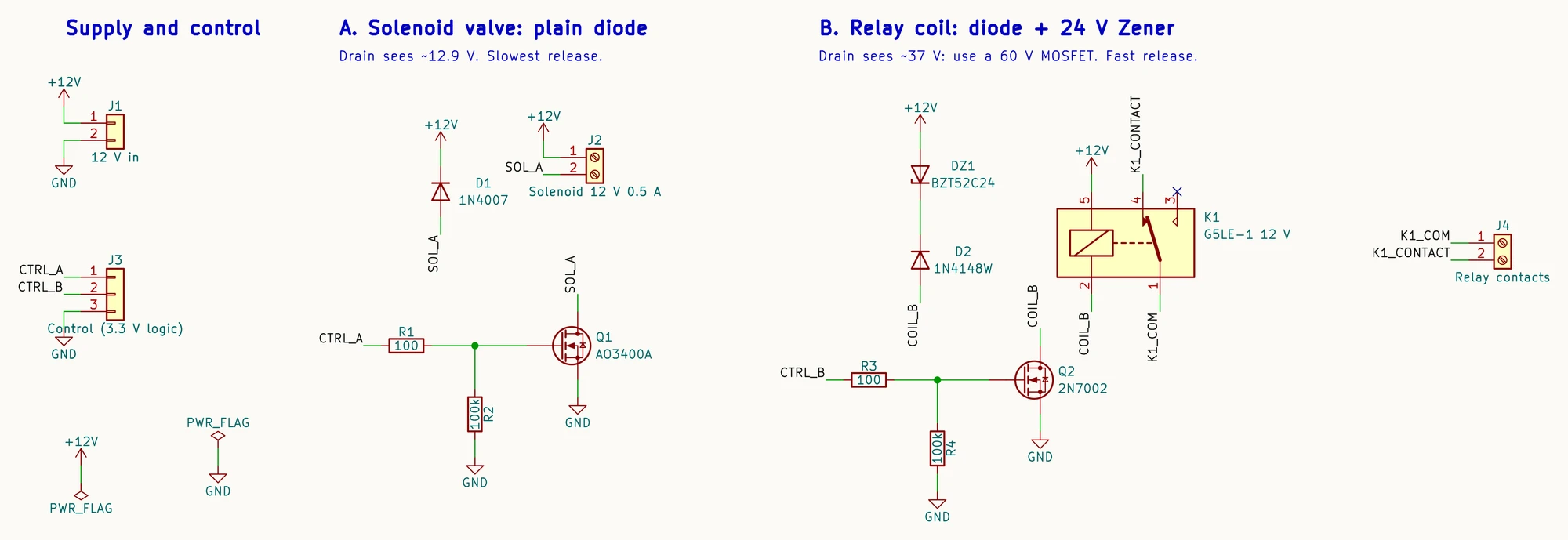
KiCad’s electrical rules check knows pin types, not what a diode is for. KiCad 9.0.9 reports 0 errors and 0 warnings on this sheet, and the same on a copy with D1 turned round, the version that shorts the 12 V supply whenever Q1 turns on. The AI PCB review page shows other mistakes that pass ERC.
The netlist does carry the answer. A short script reads KiCad’s netlist export, finds each low-side MOSFET, the load between its drain and a supply rail, and every diode on the drain net, and says what each diode does at turn-off. On the sheet above:
Q1 AO3400A: drain SOL_A, load J2 Solenoid 12 V 0.5 A
  D1 1N4007: plain flyback, cathode on +12V. Clamps at about 12.9 V; slowest release
Q2 2N7002: drain COIL_B, load K1 G5LE-1 12 V
  D2 1N4148W + DZ1 BZT52C24: diode + Zener, clamps at about 36.7 V; Q2 must be rated above that
On the copy with D1 reversed, which ERC passed:
Q1 AO3400A: drain SOL_A, load J2 Solenoid 12 V 0.5 A
  D1 1N4007: BACKWARDS. Anode on +12V, cathode on the drain.
    When Q1 turns on it shorts +12V to ground through D1 and Q1,
    and nothing clamps the turn-off spike
How PCBEditor handles flyback diodes
PCBEditor’s design check, which runs on the boards it designs, reports a diode wired across the switch (drain to source, pointing the way current flows when the switch is on) as an error, because it clamps the output instead of catching the coil’s kick. When a board it builds has a switched motor, fan, pump, solenoid, valve or relay coil with no flyback diode, it can add one: a Schottky across the load, cathode to the supply side, rated for at least 1.25 times the supply (20 V at the least) and for the load’s current. For a relay, that is the coil current, not the contact rating.
The limits: it recognises a coil from the part’s name and description, so a load described some other way gets no diode. The diode it adds is the plain kind, the slow release in the chart above; for a relay switching a heavy load, ask for a diode and a Zener and a transistor rated above the clamp. Name the diode you want in your description to be sure you get it. It does not check a diode turned round across the load, and it does not simulate the spike or the release time.
Common questions
- Which way does a flyback diode go?
- Across the coil, with the cathode (the striped end) to the positive supply side and the anode to the side the transistor switches. For a low-side N-MOSFET or NPN switch, that is cathode to +V and anode to the drain or collector. For a high-side switch, cathode to the switched output and anode to ground. Turned the other way, the diode shorts the supply through the transistor every time it turns on.
- What diode should I use for a 12 V relay?
- A small signal diode such as the 1N4148 is enough for a typical 12 V relay coil, which draws tens of milliamps; a 1N4007 works too. What matters is a reverse rating comfortably above 12 V and a current rating above the coil current. If the relay must release quickly, add a Zener in series with the diode.
- Can I use a 1N4007 as a flyback diode?
- Yes, for relays, solenoids and motors that are switched on and off, up to about 1 A of coil current. It is a slow rectifier, so it is a poor choice when the load is driven by PWM at kilohertz rates: each time the transistor turns back on, the diode conducts backwards for a moment and the transistor takes a current spike. Use a Schottky or an ultrafast diode for PWM.
- Flyback diode or Zener: which is better?
- They do different things. A diode alone keeps the switched node just above the supply, the safest for the transistor, but the current takes longest to stop. A diode with a Zener in series lets the node rise to the supply plus the Zener voltage, so the current stops several times faster. In the simulation on this page, 0.71 ms against 3.89 ms for a 12 V, 0.5 A coil. The transistor must be rated above that higher voltage.
- Is a TVS diode better than a flyback diode?
- A TVS across the transistor clamps the node at its breakdown voltage and stops the current about as fast as a diode with a Zener, but it takes the coil's energy as a pulse every switch-off, so it has to be rated for that energy and for how often it comes. A flyback diode across the coil recirculates the current instead, and is the usual choice on small boards.
- Do relay modules need a flyback diode?
- Relay modules sold for Arduino and similar boards usually carry the driver transistor and a diode across the coil already. Check the module for a diode beside the coil pins before adding one; a bare relay always needs one.
- Can I use a flyback diode on a bidirectional motor or an AC solenoid?
- Not a single diode across the load. When a motor reverses, a diode across it conducts and shorts the supply; in an H-bridge, the freewheeling path is the diode across each switch, from the MOSFET body diodes or the driver IC. On an AC coil, a diode conducts every other half cycle; use an RC snubber or a MOV or bidirectional TVS sized for the line voltage.
Draw the solenoid and relay driver in PCBEditor
The editor opens with this board described in the chat box: the valve with its 1N4007 and the relay with its diode and 24 V Zener. Change the loads and parts to yours; its design check reports a diode wired across the switch instead of the load.
Open the driver board in the editor→Sources
Every voltage, time and energy on this page is a simulation result for the coil model stated, or copied from the tool output shown. None is a bench measurement; a real coil’s inductance changes with its armature position, so measure your own part before trusting a release time.
- ngspice-39 transient simulations of the coil and clamps described on this page (one coil model: 12 V, 24 Ω, 50 mH, 5 kΩ across the winding; a switch with 200 pF and a body diode that avalanches at 60 V).
- KiCad 9.0.9 kicad-cli sch erc and netlist export, run on the two schematics described on this page.
- TE Connectivity, application note “Coil Suppression Can Reduce Relay Life” (relay release time with diode and Zener suppression).