Analog, digital and chassis ground: what to connect, and where
A datasheet with pins named AGND and DGND, a metal box with a screw marked chassis, an isolated supply with two grounds that must never meet: grounding questions arrive in several forms, and the answers don’t all point the same way. The rules below cover the three that come up most, with the reason behind each so you can tell when your board is the exception.
Last reviewed
Short answer
On most mixed-signal boards, connect a converter’s AGND and DGND pins to the same ground plane right at the chip, and keep analog and digital parts in separate areas over that one plane. Connect circuit ground to a metal chassis at one point near where the cables enter, directly or through a capacitor. Keep the two sides of an isolated supply apart; that separation is the reason it is isolated.
AGND and DGND pins on one chip
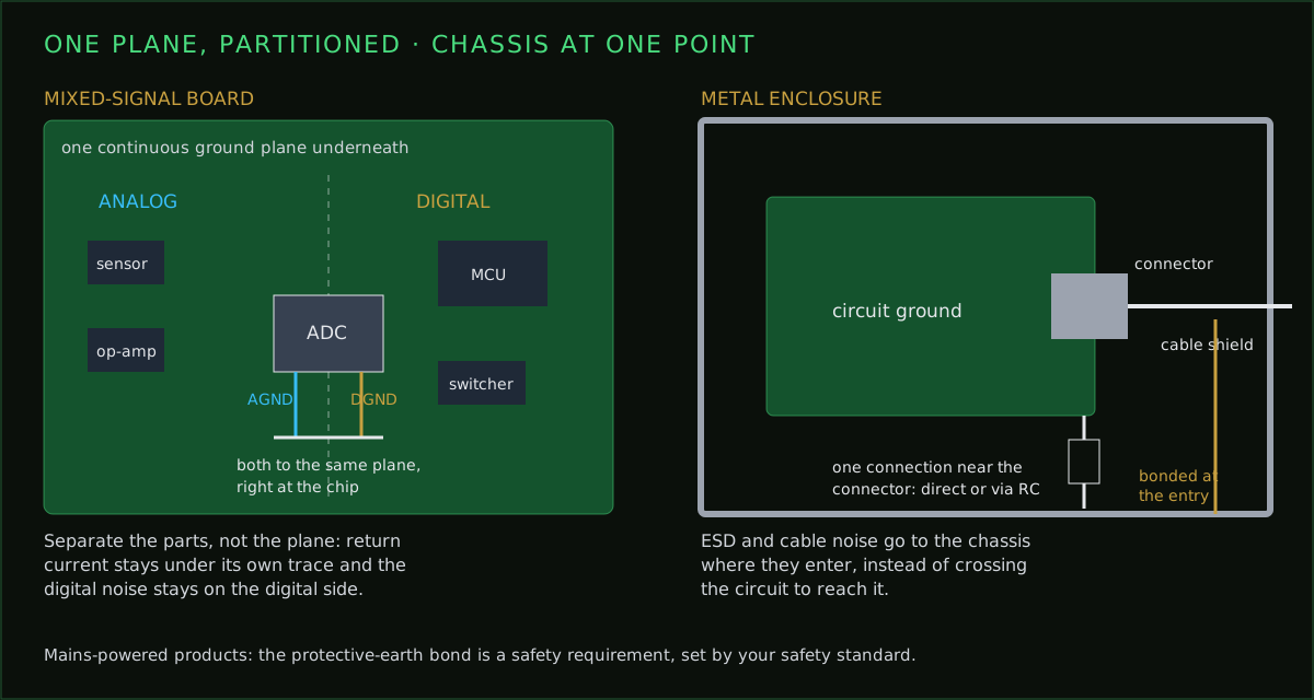
ADCs, DACs and some sensors have separate AGND and DGND pins. The names describe what each pin serves inside the chip: the sensitive analog circuitry and the digital interface. They are separate inside the package so their currents don’t share the chip’s own tiny bond wires. They are not an instruction to keep the two grounds apart on your board.
For most converters, Analog Devices’ guidance (MT-031) is to connect both pins to the same low-impedance ground plane, right at the chip, with the shortest connections you can make. The digital currents these chips draw are small, so tying DGND to the analog plane does far less harm than separating them, which would put the chip’s two grounds at different voltages.
Partition the board, not the plane
The instinct to cut the plane into an analog part and a digital part is strong, and usually wrong. The ground planes post explains why in detail: a return current follows the path under its own trace, and a slot in the plane forces it around the gap, making a loop that radiates and picks up noise.
What you separate is the parts. Put the analog circuitry on one side of the board and the digital and switching circuitry on the other, with the converter on the boundary. Route analog traces only over the analog area and digital traces only over the digital area. The plane stays whole; the noisy return currents stay on their own side because that is where their traces are.
The trace that crosses the boundary
Circuit ground and the chassis
A metal enclosure is a shield, and also the place static discharges and cable noise end up. The aim is to send that energy to the chassis where it enters, near the connectors, without it travelling through your circuit on the way.
- Connect circuit ground to the chassis at one point, close to the connector where cables enter.
- Bond cable shields to the chassis at the entry, ideally all the way round the connector, not through a long wire.
- When you need DC isolation between the circuit and the chassis, use a capacitor at that point, often with a high-value resistor in parallel to bleed off static charge.
- Avoid connecting ground to the chassis at several scattered points; currents then flow through the enclosure between them.
Mains-powered equipment in a metal case adds a safety requirement: the chassis must be bonded to protective earth as your product’s safety standard specifies. That bond is not a layout preference, and it is not something to remove to fix a hum.
Isolated supplies: keep them apart
An isolated DC/DC converter or an isolator chip exists so that the two sides don’t share a ground: for safety, to break a ground loop, or because the far side sits at a different voltage. Connecting the two grounds on the board throws that away.
- Draw the isolation barrier as a clear line on the board, with no copper, pour or trace crossing it.
- Keep the spacing across it at least what the isolator’s datasheet and your safety requirements call for. The trace spacing calculator gives IPC-2221 values as a floor; safety standards often require more.
- Give each side its own ground pour, ending well short of the barrier.
- If an EMC capacitor across the barrier is needed, use a part rated for that job and placed deliberately, not a stray pour.
What to check on your layout
- The ground plane under analog and digital areas is continuous, with no slots under high-speed traces.
- Each converter’s AGND and DGND pins reach the plane right at the chip.
- Analog traces stay over the analog area; digital and switching traces stay over theirs.
- Decoupling capacitors sit at each power pin with a short path to the plane; see the decoupling guide.
- Circuit ground meets the chassis at one deliberate point near the connectors.
- Nothing crosses an isolation barrier except the isolator itself.
Common questions
- Should AGND and DGND be connected?
- On an ADC or DAC with both pins, yes: connect both to the same low-impedance ground plane right at the chip. AGND and DGND are named for what they serve inside the chip, not as an instruction to keep them apart on your board.
- Should I split the ground plane into analog and digital?
- Usually not. A gap in the plane forces return currents to detour around it, which creates the noise you wanted to avoid. Group analog and digital parts in separate areas over one continuous plane instead.
- Should chassis ground be connected to digital ground?
- Usually at one point, near the connectors where cables enter, so ESD and cable noise go to the chassis without crossing the circuit. It can be a direct connection or a capacitor, often with a high-value resistor in parallel, when you need DC isolation.
- Should the grounds of an isolated DC/DC converter be connected?
- No. The isolation barrier is the reason to use one. Keep copper and ground pours off the barrier and keep the spacing the converter and your safety requirements call for.
- What is the difference between earth ground and chassis ground?
- Chassis ground is the metal enclosure. Earth ground is the protective earth from the mains plug. In mains-powered metal products the chassis is bonded to protective earth for safety, as your safety standard requires.
Start from one solid plane
PCBEditor gives multilayer boards dedicated ground planes and stitches the plane with vias as it routes. Describe the mixed-signal board, then check where the analog and digital parts landed before you order.
Design a mixed-signal board→Sources
These are general practice. A converter's own datasheet and evaluation-board layout take precedence for that part.
- Analog Devices: MT-031, Grounding Data Converters and Solving the Mystery of AGND and DGND.
- Henry W. Ott: Electromagnetic Compatibility Engineering (Wiley), grounding and partitioning of mixed-signal boards.